


TROUBLESHOOTING AND REPAIR
STATOR RESISTANCE TEST (continued)
Return to Section TOC Return to Section TOC Return to Section TOC Return to Section TOC
Return to Master TOC Return to Master TOC Return to Master TOC Return to Master TOC
TEST PROCEDURE
1. With the engine off, disconnect the negative bat-
tery cable. Make sure that there is nothing
plugged into the 115V and 230V receptacles.
2. Using the 5/16” nut driver, open up the control
panel and tilt out. Remove the control board
cover.
3. Refer to the “Case Cover Removal” section and
remove left side engine and stator cover panels,
and the front shroud.
4. Pull the sleeving back, and disconnect all weld
leads (W1-W6) from the SCR/Diode weld bridge
using the 7/16” nut driver and crescent wrench.
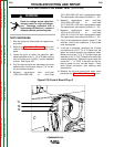
5. Locate the point at which the capacitor bank
leads are bolted to the T1,T2 & T3 leads coming
from the stator and L10953-1 exciter module.
Pull the sleeving back and disconnect the three
bolted exciter connections using a 7/16” nut dri-
ver and crescent wrench.
6. Disconnect J2 from the control board.
7. Using an Ohmmeter check for continuity
between each weld lead (W1-W6) to the T1
exciter lead. There should be no continuity
between these leads.
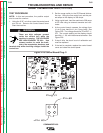
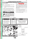
8. Check for continuity from the weld leads to the
J2 plug pins 1 & 2 at the control board. There
should be no continuity between these leads.
See Figure F.31.
9. Check for continuity from the weld leads to frame
ground. There should be no continuity between
these leads.
10. Check for continuity from J2 pins 1 & 4 to the T1
exciter lead. There should be no continuity
between these leads.
11. Check for continuity from J2 pins 1 & 4 to frame
ground. There should be no continuity between
these leads.
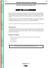
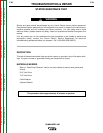
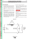
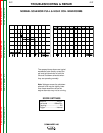
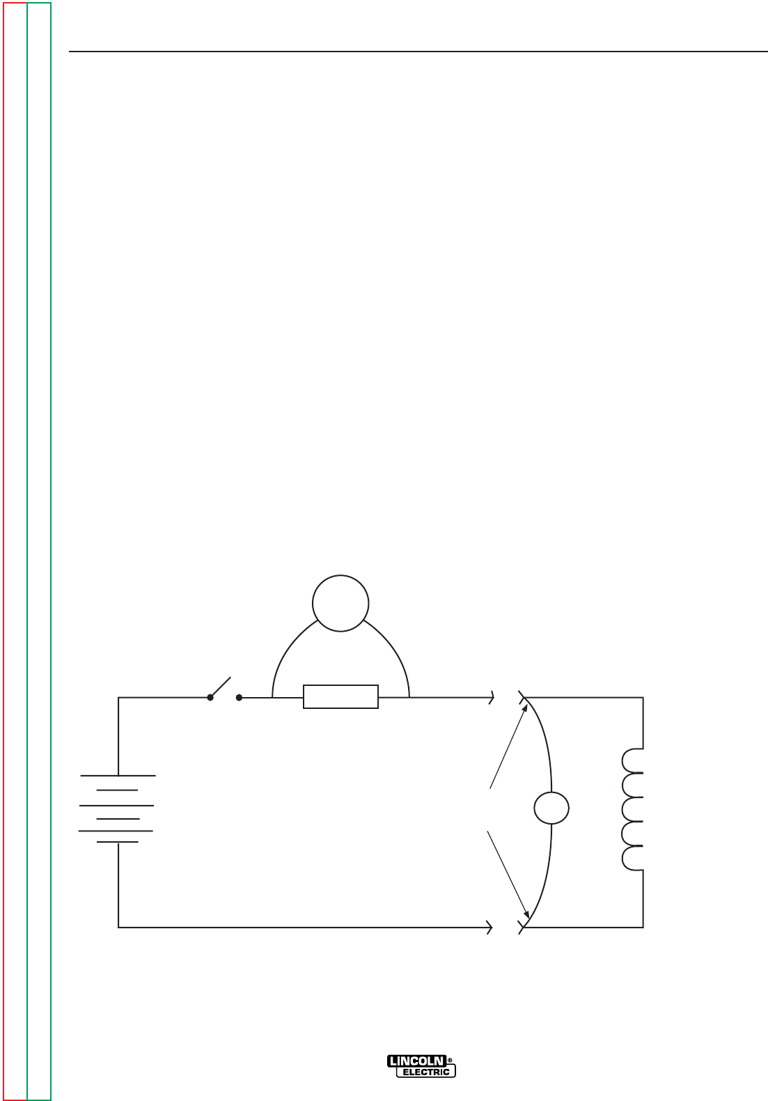
12. Construct the circuit shown below. See Figure
F.32.
F-70 F-70
J50
J51
V2
STATOR
WINDING
UNDER
TEST
VOLTAGE LEADS MUST
BE TO THE WINDING
SIDE OF THIS CONNECTION
12V
CAR
BATTERY
S1
1 OHM
300 W
V1
COMMANDER 400
Figure F.32