


TROUBLESHOOTING & REPAIR
F-96 F-96
COMMANDER 400
Return to Section TOC Return to Section TOC Return to Section TOC Return to Section TOC
Return to Master TOC Return to Master TOC Return to Master TOC Return to Master TOC
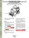
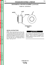
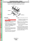
SCR REMOVAL AND REPLACEMENT (continued)
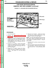
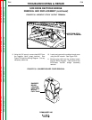
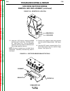
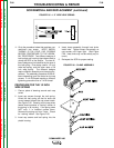
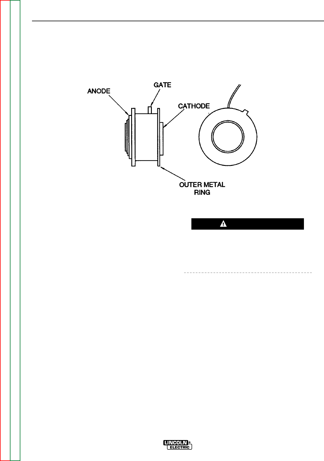
FIGURE F.43 – SCR DETAILS
SPECIAL INSTRUCTIONS
NOTE: Before disassembling the existing rectifi-
er, note toward which heat sink the outer metal
ring of the power SCR is mounted. Also, note the
positioning of the gate lead of the SCR. Failure to
reinstall the new SCR in the same orientation as
the original may result in subsequent damage to
the new SCR and other components of the
welder. See Figure F.43.
The unclamping and clamping procedure outlined
below is critical for the prevention of internal SCR
damage. Failure to follow this procedure may
result in subsequent damage of the SCR. Handle
all SCRs with care.
CAUTION