


TROUBLESHOOTING & REPAIR
F-97 F-97
COMMANDER 400
Return to Section TOC Return to Section TOC Return to Section TOC Return to Section TOC
Return to Master TOC Return to Master TOC Return to Master TOC Return to Master TOC
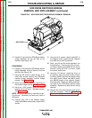
SCR REMOVAL AND REPLACEMENT (continued)
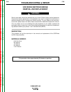
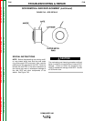
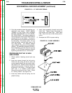
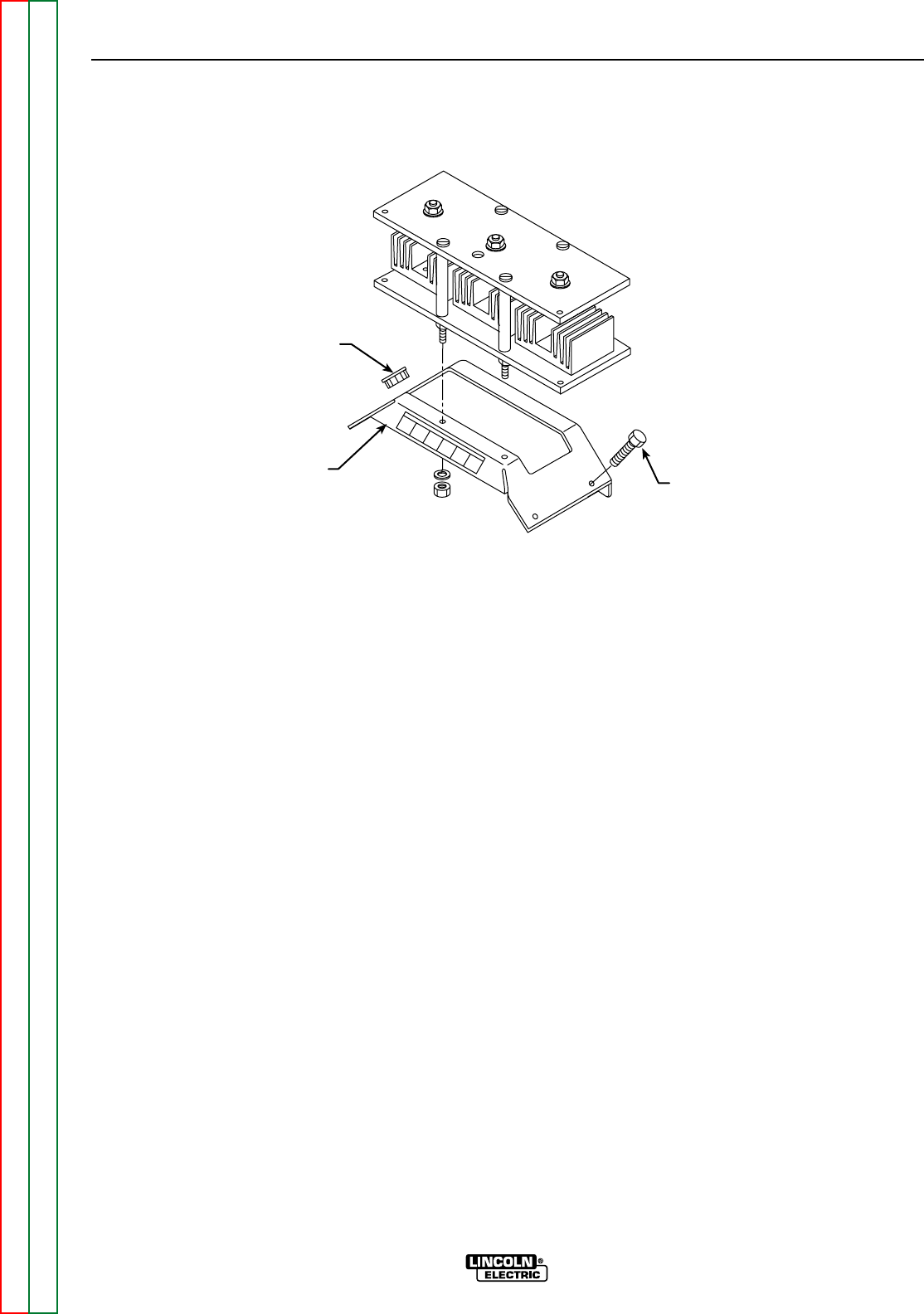
FIGURE F.44 – RECTIFIER BRIDGE ASSEMBLY BRACKET DETAILS
GROMMET
BRACKET
SCREWS (4)
PROCEDURE
1. Turn the engine off.
2. Perform the SCR/Diode Rectifier Bridge
Assembly Removal procedure.
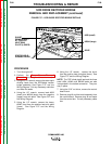
3. Using the 7/16” wrench, remove the mounting
bracket for the SCR/diode rectifier bridge
assembly bracket. See Figure F.44.
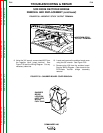
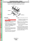
4. Alternately loosen nuts 1/2 turn each until
heat sinks are loose. Remove nuts and leaf
spring. IT IS RECOMMENDED THAT NEW
HARDWARE, LEAF SPRING AND HOUS-
ING BE USED FOR REASSEMBLY.
5. Remove the old SCR.
6. Clean the area on the heat sink around the
SCR mounting surface, using a putty knife or
similar tool. DO NOT SCRATCH THE SCR
MOUNTING SURFACE.
7. Polish each heat sink’s mounting surface
using NO. 000 fine steel wool. Wipe surface
clean with a lint-free cloth or paper towel.
8. Inspect the mounting surfaces of each new
SCR.
a. Remove all burrs and wipe clean. Do not
use steel wool or any abrasive cleanser
on the SCR mounting surfaces.
9. Apply a thin (0.001” to 0.003”) layer of PEN-
ETROX A-13 (Lincoln Electric #E2529) or
PENETROX A, heat sink compound, to each
heat sink’s SCR mounting surface.
a. Care must be used to prevent foreign
material contamination of the SCR to
heat sink junction.
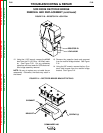
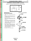
10. Place the new SCR between the heat sinks.
Be sure that the outer metal ring of the SCR
is facing toward the same heat sink as the old
SCR’s metal ring. Be sure that the roll pin of
the heat sink engages the “hole” in the SCR.
The SCR contact surfaces must sit flat
against both heat sink surfaces.