TROUBLESHOOTING & REPAIR
F-116 F-116
COMMANDER 400
Return to Section TOC Return to Section TOC Return to Section TOC Return to Section TOC
Return to Master TOC Return to Master TOC Return to Master TOC Return to Master TOC
ENGINE, STATOR/ROTOR REMOVAL AND REPLACEMENT (continued)
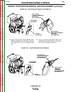
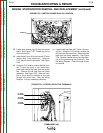
LEAD RECONNECTION CHECKLIST
Engine
❒ Engine grounding strap to engine
❒ Leads #242E and #229 to fuel level sensor
❒ Leads #224, #240, #225, and #262 to shut-
down solenoid
❒ Leads #226, #237, #227, and #254 to the
idler solenoid
❒ Leads #228 and #234 to oil pressure sensor
❒ Leads #233A and #241 to oil temperature
sensor
❒ Grounding lead to top of engine bell housing
❒ Leads #236A, #236B, #236C, #231A and
#231B to starter motor solenoid
❒ Leads #239, #285, and #238 to engine alter-
nator
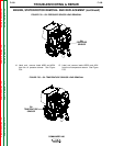
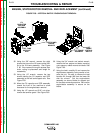
SCR/Diode rectifier bridge assembly
❒ Stator leads W1-W4, W2-W5 and W3-W6.
Exciter board
❒ Stator leads T1, T2, and T3 to studs
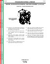
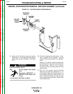
Control board/box
❒ Plug J2
❒ Leads #5 and #5A to neutral T2 stud (center)
❒ Lead #6 to T1 stud (top) and toroid assembly
(note number of turns and direction)
❒ Lead #3 to T3 stud (bottom) and toroid
assembly (note number of turns and direc-
tion)


