


Return to Section TOC Return to Section TOC Return to Section TOC Return to Section TOC
Return to Master TOC Return to Master TOC Return to Master TOC Return to Master TOC
TROUBLESHOOTING & REPAIR
F-29 F-29
COMMANDER 400
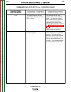
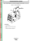
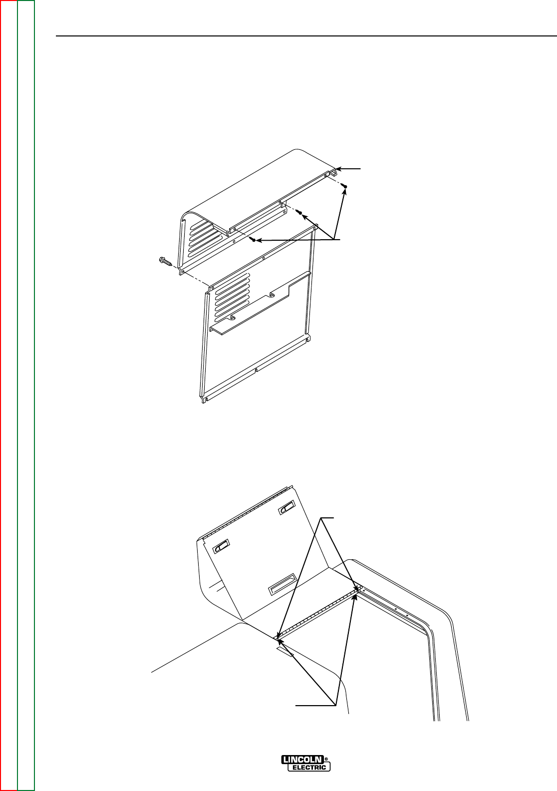
THREE SCREWS
LEFT SIDE PANEL
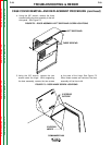
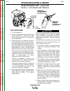
FIGURE F.2 – DOOR ASSEMBLY/LEFT SIDE PANEL SCREW LOCATIONS
4. Using the 3/8" wrench, remove the three
screws holding the door assembly to the left
side panel. See Figure F.2.
CASE COVER REMOVAL AND REPLACEMENT PROCEDURE (continued)
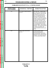
2 SCREWS
OUTSIDE
2 SCREWS
UNDER
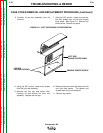
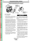
FIGURE F.3 – DOOR HINGE SCREW LOCATIONS
5. Using the 3/8" wrench, remove the two
screws under the hinge. While supporting
the door assembly, remove the two screws
at the ends of the hinge. See Figure F.3
When these screws are removed, the door
assembly will be free to fall.