


Return to Section TOC Return to Section TOC Return to Section TOC Return to Section TOC
Return to Master TOC Return to Master TOC Return to Master TOC Return to Master TOC
TROUBLESHOOTING & REPAIR
F-52 F-52
COMMANDER 400
STATOR VOLTAGE TEST (continued)
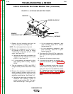
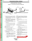
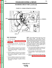
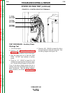
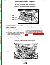
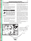
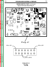
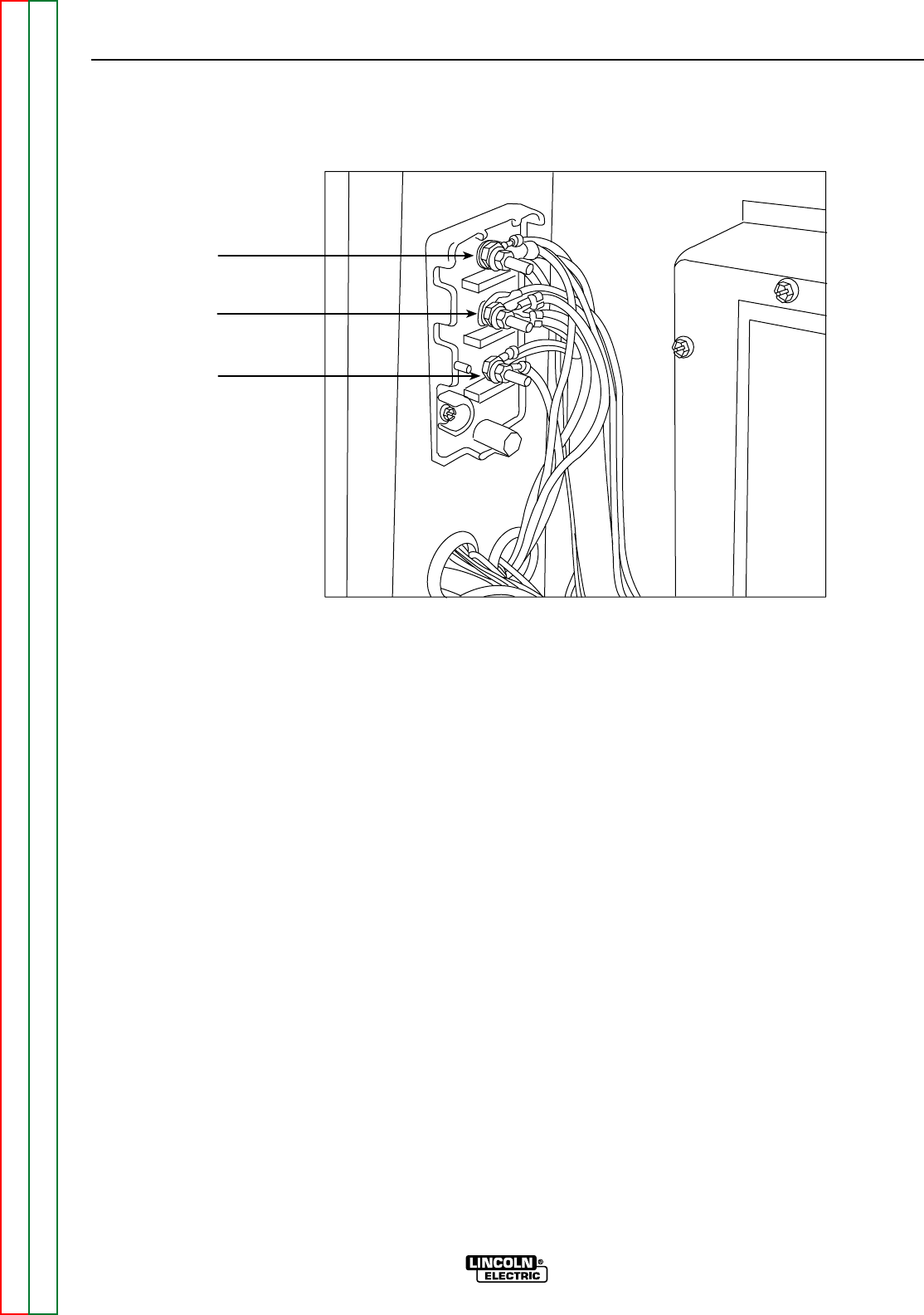
FIGURE F.23 – CONTROL BOX STUD TERMINALS
T1 STUD
#6 LEADS
T2 STUD
#5 LEADS
T3 STUD
#3 LEADS
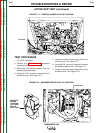
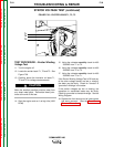
TEST PROCEDURE – Auxiliary Power
Windings Test
1. Turn off the engine.
2. Perform the Case Cover Removal
Procedure, including front shroud removal.
For this test the control box cover will be open.
3. Start the engine and run at high idle (1900
RPM). Do NOT load welding or auxiliary
power.
4. Check for 115 - 132VAC at leads 5A to 3B
located at the stud terminals inside the control
box. See the Wiring Diagram and Figure F.23.
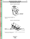
If any of the above voltage checks are low or
missing, check the associated leads for loose or
faulty connections. See the Wiring Diagram.
Then proceed to the Exciter Winding Voltage
Test.
5. Check for 230 - 250VAC at leads 6A to 3A at
the stud terminals inside the control box. See
the Wiring Diagram and Figure F.23.