


Return to Section TOC Return to Section TOC Return to Section TOC Return to Section TOC
Return to Master TOC Return to Master TOC Return to Master TOC Return to Master TOC
TROUBLESHOOTING & REPAIR
F-8 F-8
COMMANDER 400
Observe Safety Guidelines
TROUBLESHOOTING GUIDE
detailed in the beginning of this manual.
CAUTION
If for any reason you do not understand the test procedures or are unable to perform the test/repairs safely, con-
tact the Lincoln Electric Service Department for electrical troubleshooting assistance before you proceed. Call 1-
800-833-9353 (WELD).
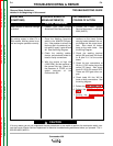
PROBLEMS
(SYMPTOMS)
POSSIBLE AREAS OF
MISADJUSTMENT(S)
RECOMMENDED
COURSE OF ACTION
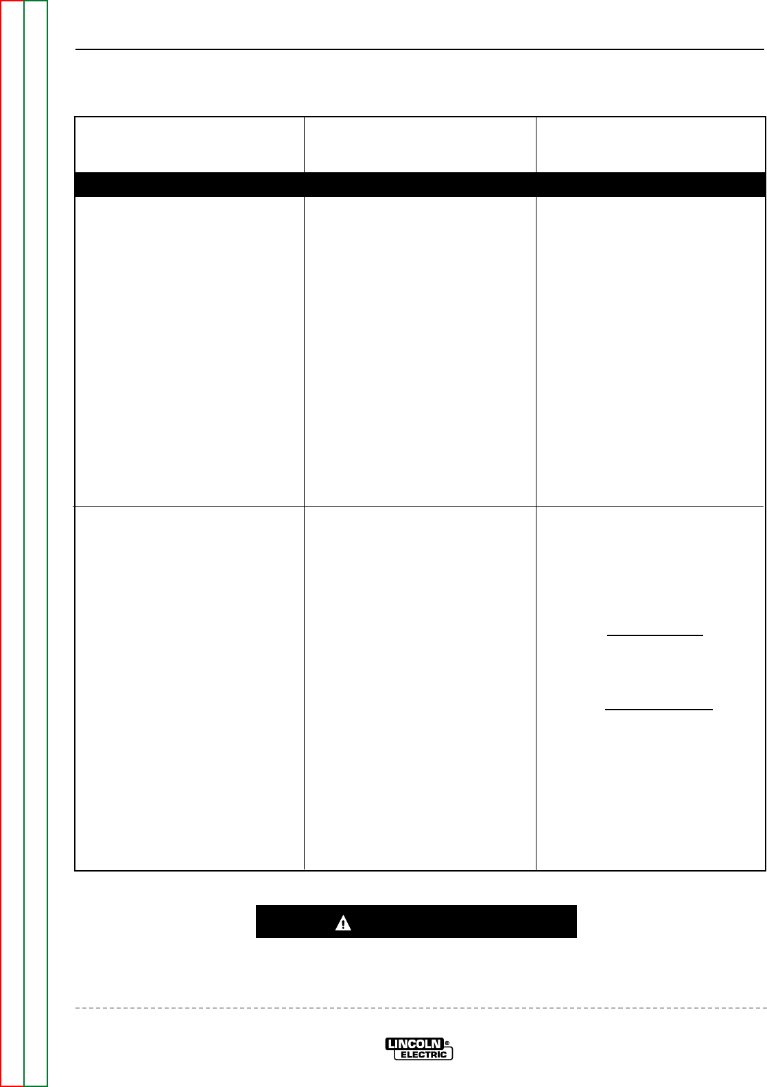
ENGINE PROBLEMS
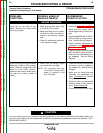
Engine will not idle down to low
speed. Machine has normal weld
and auxiliary power.
1. Make sure the Idler switch (S4)
is in the “AUTO” position.
2. Make sure there is not an exter-
nal load on either the weld ter-
minals or the auxiliary recepta-
cles.
3. Check for mechanical restriction
in the solenoid linkage.
1. Perform the Idler Solenoid Test.
2. Make sure the control board
mounting/grounding screws are
tight.
3. Check leads #226, #227, #237 &
#254 for loose or faulty connec-
tions. See the Wiring Diagram.
4. Check solenoid waveforms as
illustrated in the Oscilloscope
Waveforms Section.
5. Check to make sure that leads
#227 & #232 at the B1 & B3 ter-
minals on the control board are
not swapped. See the Wiring
Diagram.
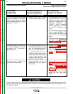
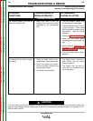
Engine will not go to high idle when
attempting to weld or use auxiliary
power. Output is normal when Idler
switch is in the “HIGH” position.
Automatic idle function works prop-
erly when the auxiliary power is
loaded.
1. Make sure the welding cables
and connections are tight.
NOTE: The automatic idler may
not function if the auxiliary
power is loaded to less
than 150 watts.
1. Check the current sensing toroid
for loose or faulty connections.
CV models only. See the Wiring
Diagram.
2. Make sure the toroid and lead
assembly are assembled cor-
rectly. CV models only
. See the
Wiring Diagram.
3. Check the shunt and associated
leads for loose or faulty connec-
tions. Stick models only
.
4. The control board may be faulty.