


TROUBLESHOOTING AND REPAIR
EXCITER CAPACITOR BANK TEST (continued)
Return to Section TOC Return to Section TOC Return to Section TOC Return to Section TOC
Return to Master TOC Return to Master TOC Return to Master TOC Return to Master TOC
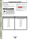
Check for voltage across capacitors.
Voltages could be high and danger-
ous. Discharge capacitors with a
high wattage (50 Ohm min.) resistor if
necessary before performing tests.
TEST PROCEDURE
1. With the engine off, disconnect the negative bat-
tery cable.
2. Refer to the “Case Cover Removal” section and
remove the left side engine and stator cover
panel.
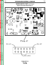
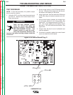
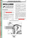
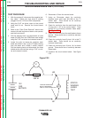
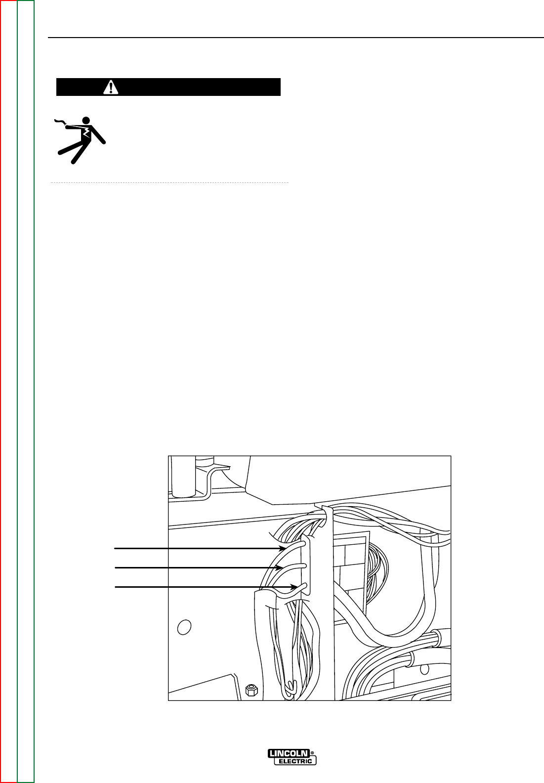
3. Locate the point at which the capacitor bank
leads are bolted to the T1, T2, & T3 leads coming
from the stator and L10953-1 exciter feedback
module. See Figure F.30.
4. Pull the sleeving back and disconnect the three
bolted exciter connections using a 7/16” nut dri-
ver and crescent wrench.
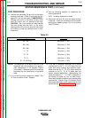
5. Measure capacitance from multi-lead
1002/1004/1006/1008 to multi-lead
1001/1003/1005/1007 with a capacitance meter.
The capacitance value should be 240 uf +/- 5%.
6. Measure capacitance from multi-lead
1018/1020/1022/1024 to multi-lead
1017/1019/1021/1023 with a capacitance meter.
The capacitance value should be 240 uf +/- 5%.
7. Measure capacitance from multi-lead
1010/1012/1014/1016 to multi-lead
1009/1011/1013/1015 with a capacitance meter.
The capacitance value should be 240 uf +/- 5%.
8. If any of the capacitance values in steps 5-7 are
incorrect, then all the capacitors in that phase
must be replaced.
9. If the test is complete, reconnect the 3 bolted
connections for the T1,T2, & T3 leads from the
stator and exciter module, and capacitor leads.
Make sure that the T1,T2, & T3 stator leads are
matched to the T1,T2,& T3 leads from the exciter
module respectively. Mismatching the leads will
cause the “---” or “CRS” to be stuck on the dis-
play at power up, and no weld output. Cover
each bolted connection with sleeving after
reconnection.
10. Reinstall the left side engine and stator cover
panels per the “Case Cover Removal” section.
F-66 F-66
COMMANDER 400
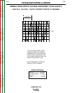
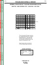
Figure F.30 Control Board Plug J1
WARNING
T1
T2
T3
WARNING