


TROUBLESHOOTING & REPAIR
F-115 F-115
COMMANDER 400
Return to Section TOC Return to Section TOC Return to Section TOC Return to Section TOC
Return to Master TOC Return to Master TOC Return to Master TOC Return to Master TOC
ENGINE, STATOR/ROTOR REMOVAL AND REPLACEMENT (continued)
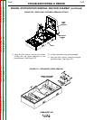
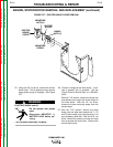
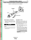
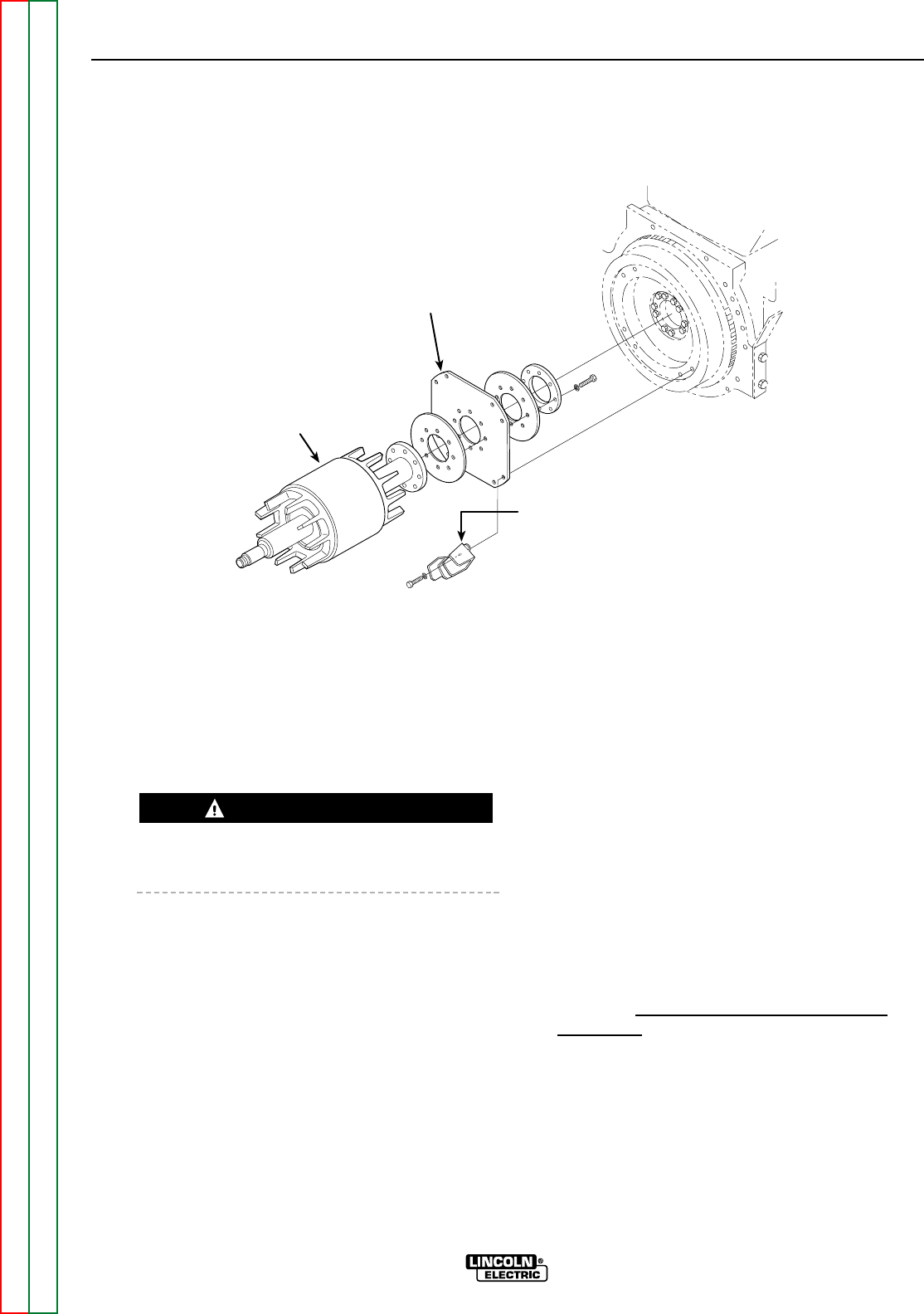
FIGURE F.62 – BLOWER PADDLE/FLEX PLATE REMOVAL
ROTOR FLEX
PLATE
ROTOR
BLOWER PADDLE
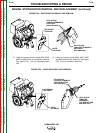
ROTOR REMOVAL PROCEDURE
1. Using the 5/8" wrench, remove the blower
paddles/rotor flex plate bolts and lock wash-
ers. See Figure F. 62. Support the rotor and
engine securely.
The rotor will be free to fall when the bolts are
removed.
2. Using the hoist, carefully remove the rotor and
flex plate assembly.
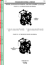
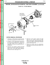
REASSEMBLY NOTES
Reassemble the rotor and stator to the
Commander 400 by carefully retracing the disas-
sembly procedure steps in reverse order. Keep
the following special points in mind as you pro-
ceed. Lead Reconnection Checklists are provid-
ed here as an aid to reassembly.
1. INSTALL ROTOR: Support the rotor with the
hoist. Install the blower paddles and flex
plate to the engine flyweel.
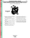
2. INSTALL STATOR: Be sure the engine is
blocked securely and the stator is supported
with the hoist. Install the stator to the engine
with the eight bolts and lock washers. Install
the bottom flywheel cover to the stator frame
with three bolts and lock washers. Install the
fan blade, making sure that it faces the prop
-
er direction
, with the fan nut and four Allen
head cap screws.
Check the air gap for .012” minimum.
WARNING