


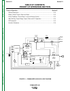
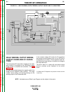
THEORY OF OPERATION
E-4 E-4
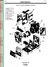
COMMANDER 400
Return to Section TOC Return to Section TOC Return to Section TOC Return to Section TOC
Return to Master TOC Return to Master TOC Return to Master TOC Return to Master TOC
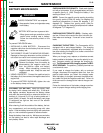
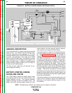
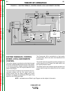
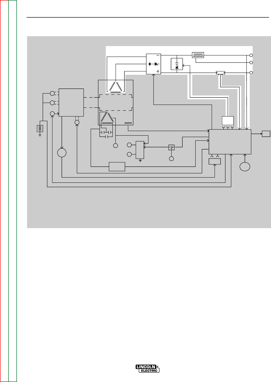
WELD WINDING, OUTPUT BRIDGE,
OUTPUT CHOKE AND CV CAPACI-
TORS
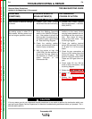
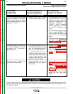
The three-phase AC output that is created in the stator
weld winding is connected to the SCR/Diode output
bridge where it is rectified and controlled. See SCR
Operation.
A choke is connected between the negative side of the
bridge and the negative output terminal. This large
inductor stores energy and provides filtering for the
welding output of the Commander 400.
In the constant voltage (CV) mode, the CV capacitors
are brought into the welding circuit via an SCR that is
activated by the CV board. These capacitors add volt-
age filtering and help maintain a constant arc voltage at
the output terminals.
1
The shunt, which is in series with the positive output
terminal, provides current feedback to the control
board.
1
CV Board and CV Capacitors are present on stick and wire
model only.
NOTE: Unshaded areas of Block Logic Diagram are the subject of discussion.
FIGURE E.4 – WELD WINDING, OUTPUT BRIDGE, OUTPUT CHOKE AND CV CAPACITORS
ENGINE ROTOR
MECHANICAL
ROTATION
EXCITER
WINDINGS
WELD
WINDINGS
SCR/DIODE
OUTPUT
BRIDGE
OUTPUT
CHOKE
CV
CAPAC
ITORS
SHUNT
POSITIVE
TERMINAL
CV
TERMINAL
TERMINAL
NEGATIVE
EXCITER
CAPACITORS
115/230VAC
RECEPTACLE
14 PIN
AMPHENOL
6 PIN
AMPHENOL
EXCITER VOLTAGE
FEEDBACK
BOARD
ENGINE
PROTECTION
BOARD
CURRENT/ MODE
SELECTOR
SWITCH
BATTERY
STARTER
ALTERNATOR
SHUTDOWN
SOLENOID
IDLER
SOLENOID
SENSORS
ENGINE
FINE
OUTPUT
CONTROL
BY-PASS
PC
BOARD
METER
CV
BOARD
MAIN
CONTROL
BOARD
REMOTE
SWITCH
42VAC
12VDC
SCR GATE SIGNALS
115VAC
FEEDBACK
F
E
E
D
B
A
C
K