


TROUBLESHOOTING & REPAIR
F-104 F-104
COMMANDER 400
Return to Section TOC Return to Section TOC Return to Section TOC Return to Section TOC
Return to Master TOC Return to Master TOC Return to Master TOC Return to Master TOC
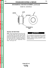
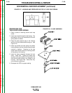
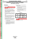
MOUNTING OF STUD TYPE DIODES TO ALUMINUM
HEAT SINKS (continued)
PROCEDURE
1. Turn the engine off.
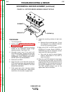
2. Perform the SCR/Diode Bridge Removal
Procedure.
3. Loosen the appropriate diode nut and
remove the diode that is to be replaced.
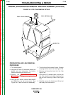
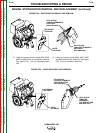
4. Clean the area on the heat sink around the
diode mounting surface using a putty knife or
similar tool. DO NOT SCRATCH THE DIODE
MOUNTING SURFACE.
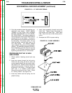
5. Polish each heat sink’s mounting surface
using No. 000 fine steel wool. Wipe the sur-
face clean with a lint-free cloth or paper
towel.
6. Inspect the mounting surfaces of each new
diode. Remove all burrs and wipe clean. Do
not use steel wool or any abrasive cleanser
on the diode mounting surface.
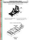
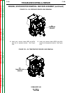
7. Apply a thin (0.003” to 0.007”) uniform layer
of E1868 (Dow Corning 340) heat sink com-
pound to the heat sink mounting surface.
a. Do not apply compound to the diode stud
or mounting threads.
b. The diode threads must be clean and
free of defects so that the nut can be fin-
ger tightened before applying torque. A
“slip” type torque wrench must be used to
tighten the diode nut.
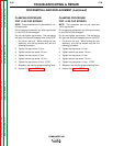
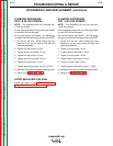
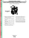
8. Tighten the diode nuts to the specifications in
the following table.
a. Start the nuts for diodes with steel studs
by hand and then torque them according
to the following table.
b. Run the nuts for diodes with copper studs
on all the way by hand then torque them
according to Table F.4 below.
c. Turn the nuts a minimum of 1/2 turn more
while torquing.
DIODE STUD FOOT- INCH-
SIZE POUNDS POUNDS
3/4-16 25-27 300-324
3/8-24 10±.5 125+0/-5
1/4-28 22-25
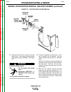
9. Perform SCR/Diode Bridge Replacement
Procedure.
10. Install the case top and sides.
Table F.4