


Return to Section TOC Return to Section TOC Return to Section TOC Return to Section TOC
Return to Master TOC Return to Master TOC Return to Master TOC Return to Master TOC
A-2 A-2
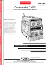
COMMANDER 400
INSTALLATION
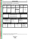
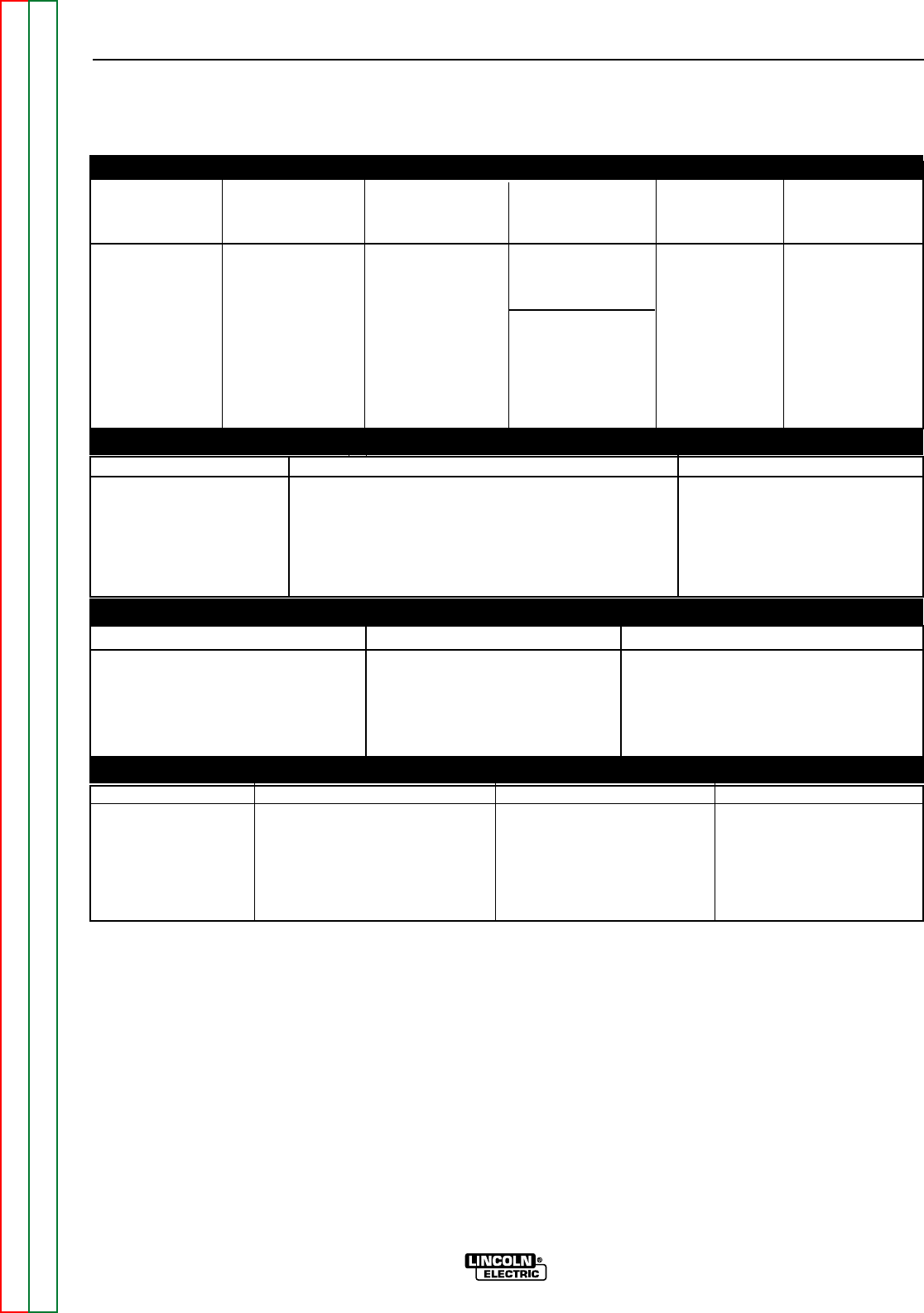
TECHNICAL SPECIFICATIONS - Commander 400
Make/Model Description Speed (RPM) Displacement Starting Capacities
System
Deutz 3 cylinder High Idle 1900 173 cu. in 12VDC battery Fuel: 25 gal.
F3L 912 Diesel 44.2 HP(33kw) Low Idle 1350 (2.827 L) & Starter 94.6 L
Engine @ 1800 RPM Full Load 1800
Bore x Stroke Oil: 8.5 Qts.
8.04 L
3.94” x 4.72”
(100mm x 120mm)
INPUT - DIESEL ENGINE
RATED OUTPUT - WELDER
HEIGHT
2
WIDTH DEPTH WEIGHT
42.0 in. 31.5 in. 63.1 in. 1650 lbs.(748 kg)
(Stick model)
1066.8 mm 800.1 mm 1602.7 mm 1683 lbs.(763 kg)
(Stick & Wire model)
OUTPUT - WELDER AND GENERATOR
Duty Cycle Welding Output Volts at Rated Amps
100%
400 amps (DC Constant Current) 40 volts
400 amps (DC Constant Voltage) 40 volts
60%
500 amps (DC Constant Current) 40 volts
500 amps (DC Constant Voltage) 40 volts
Welding Range Open Circuit Voltage Auxiliary Power
1
40 - 575 Amps 64-74 OCV 120/240 VAC
in 7 Ranges (Stick model) 10,000 Watts, 60 Hz.
or 8 Ranges
(Stick & Wire model)
@1915 RPM 100% Duty Cycle
PHYSICAL DIMENSIONS
1. Output rating in watts is equivalent to volt-amperes at unity power factor.
Output voltage is within +/- 10% at all loads up to rated capacity. When welding, available auxiliary power will be reduced.
2. Top of Enclosure. Add 6.64” (168.7mm) for exhaust.