


TROUBLESHOOTING AND REPAIR
CONTROL BOARD POWER SUPPLY TEST (continued)
Return to Section TOC Return to Section TOC Return to Section TOC Return to Section TOC
Return to Master TOC Return to Master TOC Return to Master TOC Return to Master TOC
TEST PROCEDURE
NOTE 1: In this test procedure, the positive output
stud is used for common.
NOTE 2: This test procedure does not test the engine
control power supply portion of the control
board.
1. Using the 5/16” nut driver, open the control panel
and tilt out. Remove the control board cover.
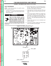
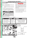
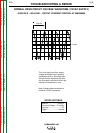
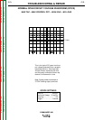
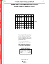
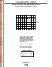
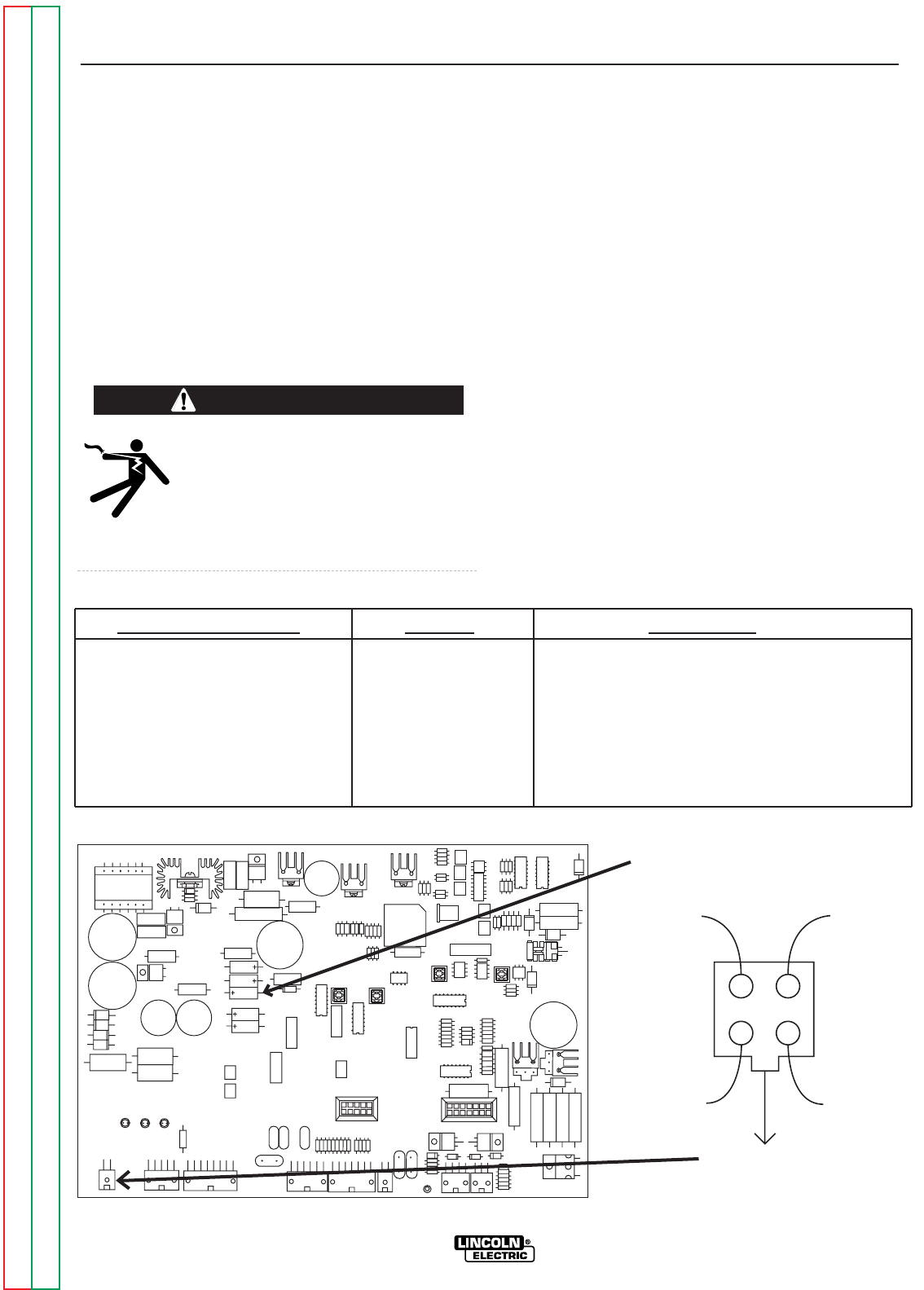
2. Using the control PC board layout, locate capaci-
tor C112 (Figure F.31) and scrape the environmen-
tal coating off the negative lead. Start the
machine.
There are high voltages present inside
the control box while the machine is
running. THE VOLTAGES ARE HIGH
ENOUGH TO KILL. Use extreme cau-
tion to avoid the backside of the recep-
tacles, breakers, and terminal strip while checking
voltages inside the control box.
3. Refer to the Stator Voltage Test, step 10, to test
the E1-E2 stator winding that powers the control
PC board. If the voltage is correct, proceed to
step 4. If the voltage is incorrect, shut down the
machine, unplug J2, restart the machine, and
check the voltage again at J2 pins 1 to 4. If the
voltage is still incorrect, abort the “Control Board
Power Supply Test” and proceed to the “Stator
Resistance Test”.
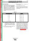
4. With the machine running, measure the voltages at
the control board per the following table.
5. If any of the voltage checks in the Table F.2 below
are incorrect, replace the control board.
6. If the test is complete, replace the control board
cover and close the control panel.
WARNING
F-68 F-68
Measurement Point Voltage Description
J5 pin 2 to common 15 VDC +/- 5% +15V supply for display
J4 pin 6 to common 10 VDC +/- 5% +10V supply for weld control & exciter module
J5 pin 7 to common 5 VDC +/- 5% +5V supply for microprocessor
C112 neg. lead to common -10 VDC +/- 5% -10V supply for weld control
J8 pin 2 to J8 pin 3 24 VDC +/- 5% +24V supply for 2-4 circuit
J20 pin 3 to J20 pin 4 15 VDC +/- 5% +15V supply for CV SCR gate drive circuit
COMMANDER 400
Table F.2
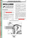
Figure F.31 Control Board Plugs C112 & J2
J2
J6
J5
J8
J7
J1
J4
J22
J20
C112
Pin #2
Pin #3
Plug J2
Pin #1
Pin #4
C112