


TROUBLESHOOTING & REPAIR
F-90 F-90
COMMANDER 400
Return to Section TOC Return to Section TOC Return to Section TOC Return to Section TOC
Return to Master TOC Return to Master TOC Return to Master TOC Return to Master TOC
SCR/DIODE RECTIFIER BRIDGE
REMOVAL AND REPLACEMENT (continued)
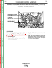
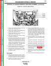
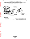
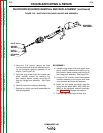
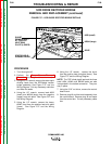
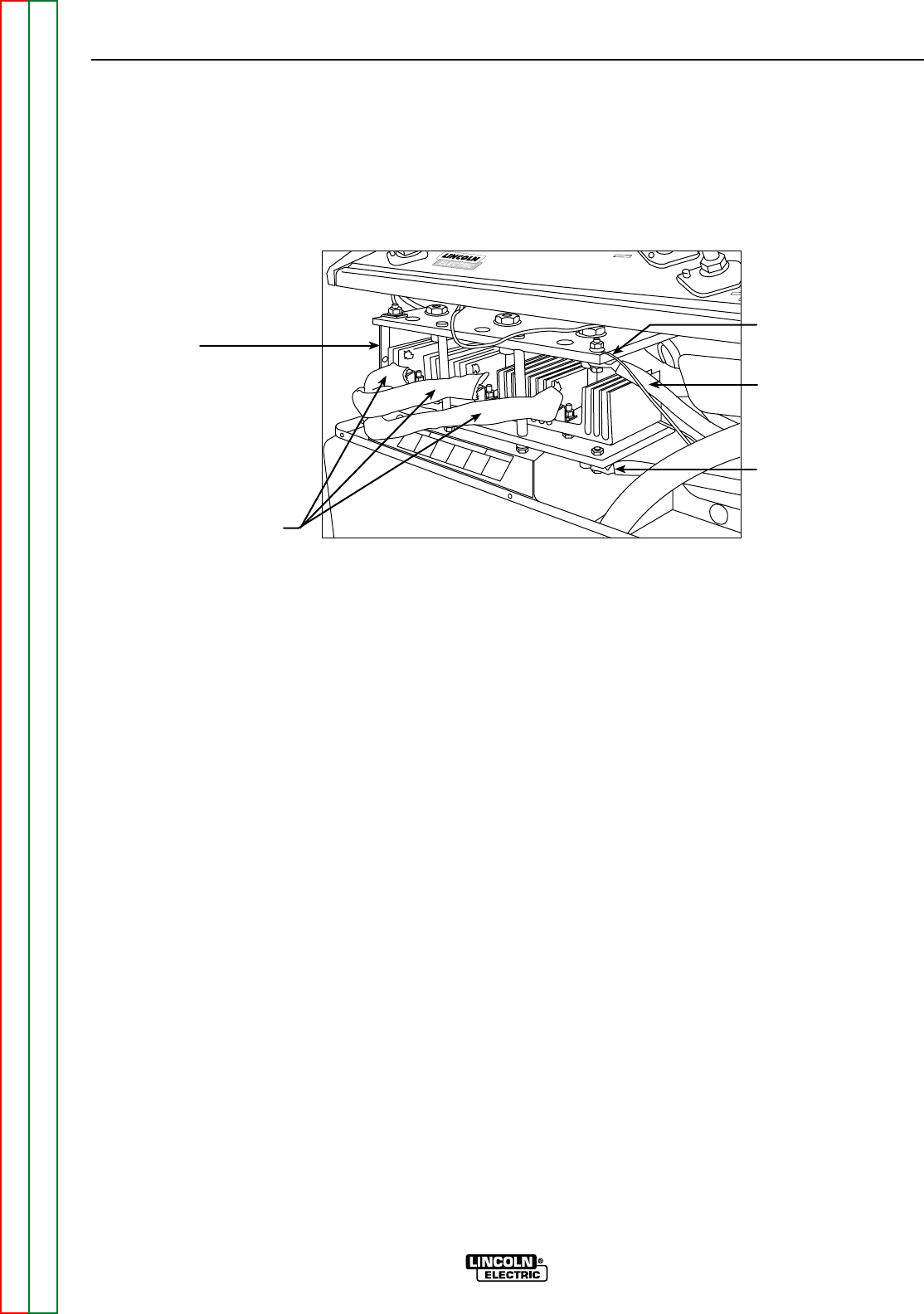
FIGURE F.37 – SCR/DIODE RECTIFIER BRIDGE DETAILS
#209 (small)
#209A (large)
#204C
STATOR WELD
WINDING LEADS
SHUNT
REMOVE BOLT
AT POSITIVE
HEAT SINK
PLATE (LOWER)
COMMANDER 400
STICK and WIRE
STICK and WIRE
WIRE
WIRE
STISTI
+
PROCEDURE
1. Turn the engine off.
2. Perform the Case Cover Removal
Procedure (including front shroud removal).
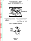
3. Using the 1/2" wrench, remove the stator weld
winding leads from the SCR/diode rectifier
bridge assembly. See Figure F.37 and the
Wiring Diagram. Cut any necessary cable ties
and clear the leads.
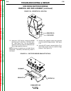
4. Using the 1/2" wrench, remove lead #209
(small) and #209A (large) from the negative
(upper) heat sink plate. See Figure F.37 and
the Wiring Diagram.
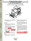
5. Using the 1/2" wrench, remove the heavy
#204C lead from the positive heat sink plate
(lower). See Figure F.37 and the Wiring
Diagram.
6. Using the 1/2" wrench, remove the shunt
from the positive heat sink plate (lower). See
Figure F.37 and the Wiring Diagram.
NOTE: The "DD" diode pigtail lead and the three
small #204, #204A and #204B leads are also
incorporated in the bolted connection. They can
stay in place.
7. Using the 5/16" nut driver, remove the control
board cover.
8. Remove plug J6 and the toroid assembly from
the control board. Remove plug J6 and leads
from the control box. Cut any necessary cable
ties.