


TROUBLESHOOTING & REPAIR
F-111 F-111
COMMANDER 400
Return to Section TOC Return to Section TOC Return to Section TOC Return to Section TOC
Return to Master TOC Return to Master TOC Return to Master TOC Return to Master TOC
ENGINE, STATOR/ROTOR REMOVAL AND REPLACEMENT (continued)
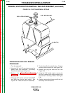
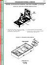
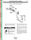
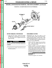
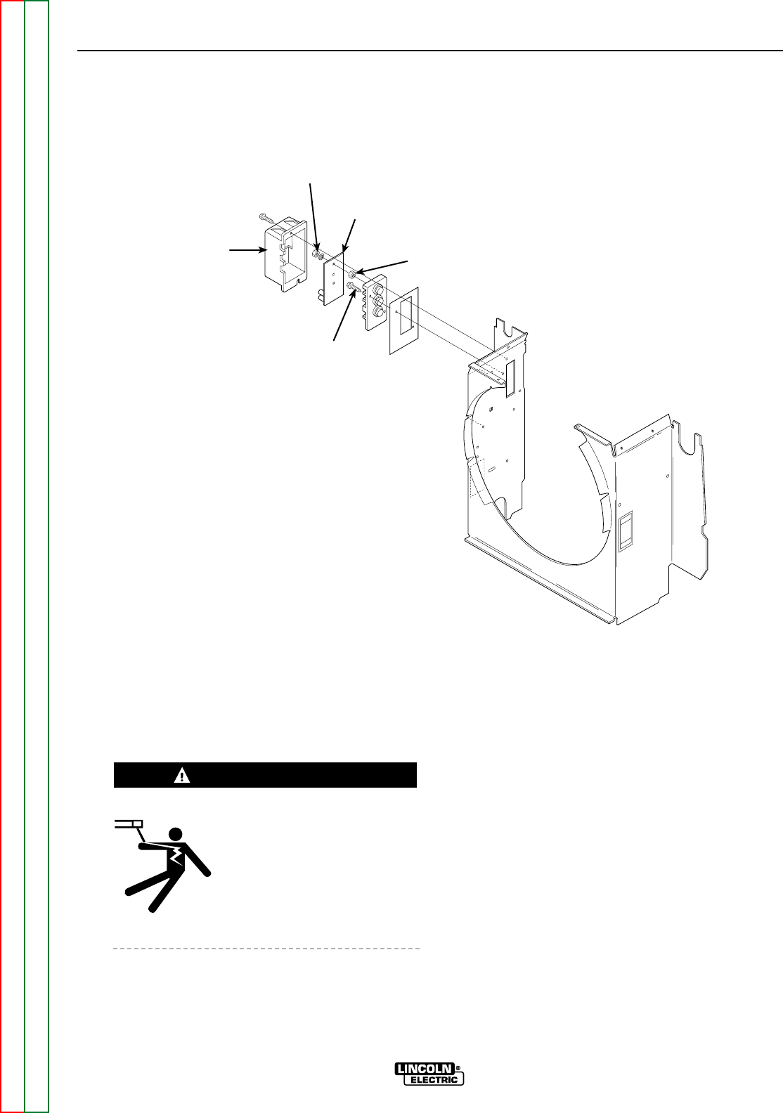
FIGURE F.57 – EXCITER BOARD COVER REMOVAL
EXCITER
BOARD
COVER
MOUNTING
NUTS (3)
EXCITER
BOARD
BRASS
NUTS (3)
MOUNTING
SCREW
25. Using the 3/8" nut driver, remove the exciter
board cover. This is sealed and may require
some gentle prying to dislodge. See Figure
F.57.
ELECTRIC SHOCK can kill.
• Do not operate with panels
open.
• Disconnect NEGATIVE (-)
BATTERY LEAD before ser-
vicing.
• Do not touch electrically live parts.
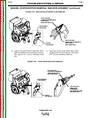
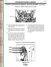
26. Check for voltage at the three studs . If volt-
age is present, do not proceed. Call the
Lincoln Electric Service Dept. at 1-800-833-
9353.
With the 7/16" wrench, remove the three nuts
and washers that mount the exciter board to
the three studs. With the 1/4" nut driver,
remove the lower mounting screw from the
exciter board.
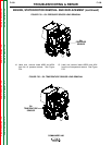
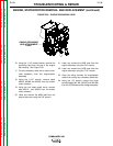
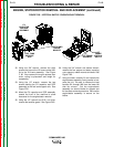
27. With the 7/16" wrench, remove the three
brass nuts and label and remove the T1, T2
and T3 stator leads (only) from the studs. Cut
any necessary cable ties. With the 5/16’ nut
driver, remove the screws and drop the case
front to access the control box. Remove the
control board cover.
WARNING