


Return to Section TOC Return to Section TOC Return to Section TOC Return to Section TOC
Return to Master TOC Return to Master TOC Return to Master TOC Return to Master TOC
TROUBLESHOOTING & REPAIR
F-12 F-12
COMMANDER 400
TROUBLESHOOTING GUIDE Observe Safety Guidelines
detailed in the beginning of this manual.
CAUTION
If for any reason you do not understand the test procedures or are unable to perform the test/repairs safely, con-
tact the Lincoln Electric Service Department for electrical troubleshooting assistance before you proceed. Call 1-
800-833-9353 (WELD).
PROBLEMS
(SYMPTOMS)
POSSIBLE AREAS OF
MISADJUSTMENT(S)
RECOMMENDED
COURSE OF ACTION
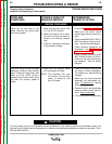
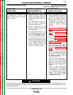
FUNCTION PROBLEMS
The welding arc is “cold.” The
engine runs normally. The auxiliary
power is normal.
1. Check for loose or faulty con-
nections at the weld output ter-
minals and welding cable con-
nections.
2. The welding cables may be too
long or coiled, causing an
excessive voltage drop.
3. Check to make sure that the
machine settings match the
weld application.
4. If a remote control unit is not
connected to the machine, make
sure the Local/Remote switch
(S1) is in the “LOCAL” position.
5. If the remote control unit is con-
nected, and the machine oper-
ates normally when the switch is
in the “LOCAL” position, the
remote control cable or unit may
be faulty. Check or replace.
1. Using a voltmeter, check for the
correct OCV at the weld termi-
nals. If the correct voltage is
present, then check for loose
connections on the heavy cur-
rent carrying leads inside the
machine. See the Wiring
Diagram.
2. If the OCV is low, perform the
Engine Throttle Adjustment
Test.
3. Perform the SCR/Diode Bridge
Test.
4. Perform the Stator Voltage Test.
5. Perform the Range Switch Test.
6. Perform the Fine Control
Potentiometer Test.
7. Check fro poor connections at
the J1 molex plug at the control
board and at the shunt. Also,
perform the Shunt Calibration
Test.
8. Check for poor connections
along lead #204A at the diode
bridge and at J6 pin 4 molex at
the control pc board. This is
control board common.
9. Check for poor connections at
J6 pins 1, 2 & 3 molex plug at
the control board. Also check
leads G1, G2 & G3 to each
SCR. These are SCR gate drive
outputs.
10. Check for poor connections
along lead #207 at the negative
CC output stud, and at the J6
pin 10 molex plug at the control
board. This is CC arc voltage
feedback input. Will not affect
welding in the CV tap.