


TROUBLESHOOTING & REPAIR
F-100 F-100
COMMANDER 400
Return to Section TOC Return to Section TOC Return to Section TOC Return to Section TOC
Return to Master TOC Return to Master TOC Return to Master TOC Return to Master TOC
SCR REMOVAL AND REPLACEMENT (continued)
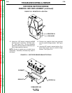
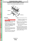
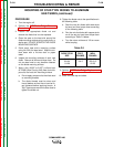
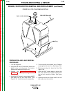
FIGURE F.47 – HOUSING AND PRESSURE PAD FOR 5/8” WIDE LEAF SPRING
PROCEDURE FOR
THE 5/8 INCH WIDE SPRING
1. Place a piece of sleeving around each cap
screw.
2. Insert cap screws through the leaf spring. The
leaf spring is flat so the orientation of the leaf
spring does not matter.
3. Place the steel pressure pad in the housing
with the 1/8 inch wide standoff facing up. See
Figure F.47.
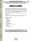
4. Insert cap screws and leaf spring into plastic
housing being sure that the steel pressure pad
remains in position. Pressing on the cap
screw heads should produce a rocking action
of the spring in its housing.
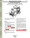
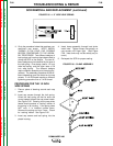
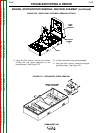
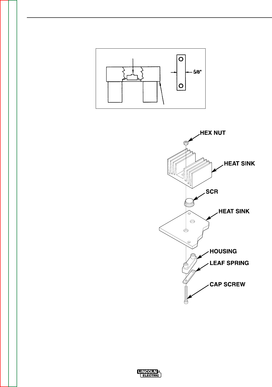
5. Insert the clamp assembly through the heat
sinks. Install nuts. Tighten the clamp nuts
equally on the cap screws until finger tight. Be
sure that the leaf spring is not cocked in the
housing. See Figure F.48. Heat sinks may
not be exactly as pictured.
6. Reinspect the SCR for proper seating.
FIGURE F.48 – CLAMP ASSEMBLY