


TROUBLESHOOTING & REPAIR
F-53 F-53
COMMANDER 400
Return to Section TOC Return to Section TOC Return to Section TOC Return to Section TOC
Return to Master TOC Return to Master TOC Return to Master TOC Return to Master TOC
STATOR VOLTAGE TEST (continued)
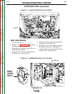
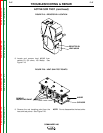
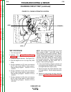
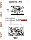
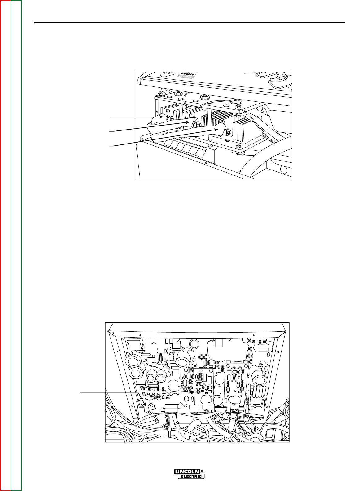
FIGURE F.24 – SCR/DIODE RECTIFIER BRIDGE LEADS
COMMANDER 400
STICK and WIRE
STICK and WIRE
WIRE
WIRE
STISTI
+
W2/W5
W1/W4
W3/W6
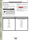
TEST PROCEDURE – Weld and PC
Board Windings Test
7. Check for 48-55VAC at leads W1/W4 to leads
W2/W5 located at the SCR/Diode Bridge. See
Figure F.24 and the Wiring Diagram.
8. Check for 48 - 55VAC at leads W2/W5 to leads
W3/W6 located at the SCR/Diode Bridge. See
Figure F.24 and the Wiring Diagram.
9. Check for 48 - 55VAC at leads W3/W6 to leads
W1/W4 located at the SCR/Diode Bridge. See
Figure F.24 and the Wiring Diagram.
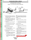
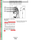
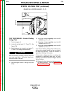
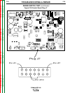
10. Check for approximately 42VAC at leads E1
to E2 located at plug J2 on the control board.
See Figure F.25. Do not remove the plug from
the control board.
If any of the above voltage checks are low or
missing, check the associated leads for loose or
faulty connections. See the Wiring Diagram.
Then proceed to the Exciter Winding Voltage
Test
FIGURE F.25 – CONTROL BOARD PLUG J2 LOCATION
PLUG J2
P e l 9 9 6