


F-36
TROUBLESHOOTING AND REPAIR
F-36
POWER WAVE 455/POWER FEED 10
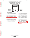
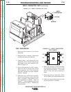
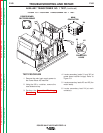
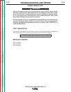
FIGURE F.7 — INPUT CONTACTOR
TEST POINTS.
6. When the contactor is NOT activated,
the resistance should be infinite or very
high across the contacts. If the resis-
tance is low, the input contactor is
faulty.
7. Reconnect the four leads (601, 601A,
X4, and X4A) to the input contactor coil.
8. Install the input access door and case
top using the 3/8 in. nutdriver.
TEST PROCEDURE
1. Remove input power to the Power
Wave 455.
2. Using the 3/8 in. nutdriver, remove the
input access panel and case top.
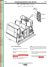
3. Locate, mark, and remove the four
leads (601, 601A, X4 and X4A) that are
connected to the input contactor coil.
Refer to Figure F.6.
4. Using the external 24 VAC supply,
apply 24 VAC to the terminals of the
input contactor coil. If the contactor
does NOT activate, the input contactor
is faulty. Replace.
5. With the input contactor activated,
check the continuity across the three
sets of contacts. (Zero ohms or very
low resistance is normal). Refer to
Figure F.7. If the resistance is high, the
input contactor is faulty. Replace the
input contactor.
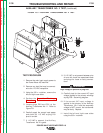
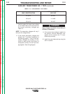
FIGURE F.6 — INPUT CONTACTOR COIL.
INPUT
CONTACTOR
X4/X4A
601/601A
INPUT CONTACTOR TEST
(continued)
L3
L2
L1
T3
T2
T1
Return to Section TOC Return to Section TOC Return to Section TOC Return to Section TOC
Return to Master TOC Return to Master TOC Return to Master TOC Return to Master TOC