


F-30
TROUBLESHOOTING AND REPAIR
F-30
POWER WAVE 455/POWER FEED 10
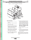
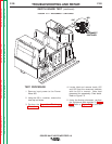
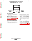
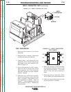
3. With the analog ohmmeter, measure
the resistance between the positive and
negative output terminals. Refer to
Figure F.4. IMPORTANT: The positive
(+) meter probe must be attached to the
positive (+) output terminal and the
negative (-) meter probe must be
attached to the negative (-) output ter-
minal.
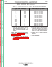
4. If the reading is more than 200 ohms,
the output rectifier modules are not
shorted. If the reading is less than 200
ohms, one or more of the rectifier mod-
ules are shorted. Refer to the
Output
Rectifier Module Replacement
Procedure.
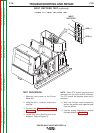
TEST PROCEDURE
1. Remove main input supply power to the
Power Wave 455.
NOTE: Later code machines have a 50
ohm resistor across the welding output ter-
minals. It will be necessary to remove the
case sides and
Perform the Input Filter
Capacitor Discharge Procedure.
Remove
and insulate one of the resistor leads (#
202A or #206A) from the appropriate weld-
ing output terminal. See the wiring diagram.
2. Remove any output load that may be
connected to the Power Wave 455.
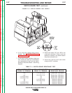
FIGURE F.4 — OUTPUT RECTIFIER TEST.
NEGATIVE (-)
OUTPUT
TERMINAL
POSITIVE (+)
OUTPUT
TERMINAL
OUTPUT RECTIFIER TEST
(continued)
Return to Section TOC Return to Section TOC Return to Section TOC Return to Section TOC
Return to Master TOC Return to Master TOC Return to Master TOC Return to Master TOC