


A-11
INSTALLATION
POWER WAVE 455/POWER FEED 10
A-11
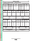
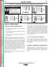
DIP SWITCH SETUP
SETTING DIP SWITCHES IN THE
CONTROL BOX
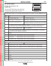
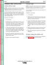
There are two DIP switch banks on the mother board
of the Control Box. They are labeled S1 and S2 and
are located and oriented as shown in Figure A.3.
Return to Section TOC Return to Section TOC Return to Section TOC Return to Section TOC
Return to Master TOC Return to Master TOC Return to Master TOC Return to Master TOC
FIGURE A.3
S1
ON
1 2 3 4 5 6 7 8
S2
ON
1 2 3 4 5 6 7 8
S1 DIP Switch Bank on Control Box Motherboard (For software version S24004-2 only)
Switch Off On
1 US 4-Step Trigger Logic Euro 4-Step Trigger Logic
2 WFS Display = inches/minute WFS Display = meters/minute
3 Left Display is always preset WFS Left Display is preset WFS when weld current is not flowing
Left Display is actual weld current when weld current is flowing
CC modes override this switch regardless of position. Left Display is always preset weld cur-
rent when weld current is not flowing and actual weld current when weld current is flowing
4 Run-in = Minimum Speed Available Run-in = weld WFS
If any option containing a Run-in setting is connected to the motherboard, it automatically
overrides this switch regardless of position.
5 Spare
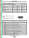
6 Acceleration, MSB (Sets acceleration rate for wire drive) see below
7 Acceleration (Sets acceleration rate for wire drive) see below
8 Acceleration, LSB (Sets acceleration rate for wire drive) see below
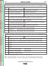
S2 DIP Switch Bank on Control Box Motherboard (For software version S24004-2 only)
Switch Off On
1 Network Group ID, MSB (Assigns Control Box to a specific group) (Off is factory setting)
2 Network Group ID, LSB (Assigns Control Box to a specific group ) (Off is factory setting)
3 Spare
4 Spare
5 Spare
6 Spare
7 Spare
8 Reserved
Note: the factory shipped settings for all of the S1 and S2 switches is “OFF”.