


F-60
TROUBLESHOOTING AND REPAIR
F-60
POWER WAVE 455/POWER FEED 10
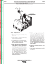
feeder/Control Box end. Refer to Figure
F.16 and Table F-6.
4. If any conductor resistance measures
greater than 1.0 ohm, the cable is
faulty and should be replaced. If the
resistance between any two conductors
or any conductor and the amphenol
body is less than 0.5M ohms, the cable
is faulty and should be replaced.
5. Connect the control cable amphenols to
the wire feeder and power source.
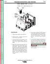
TEST PROCEDURE
1. Disconnect the input power to the
Power Wave 455 machine.
2. Disconnect the control cable amphe-
nols from the power source and the
wire feeder.
3. Using the ohmmeter measure the resis-
tance of the individual control cable
leads from the amphenol on the power
source end to the amphenol on the wire
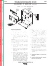
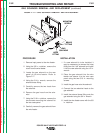
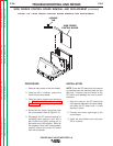
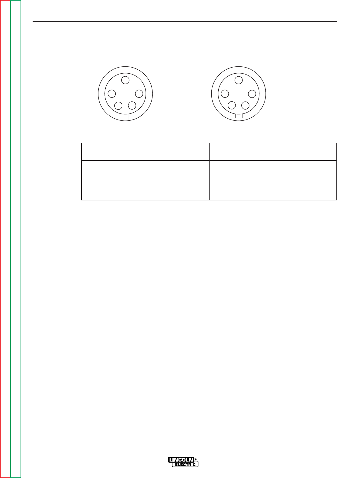
FIGURE F.16 — CABLE CONTINUITY TEST.
WIRE FEEDER END POWER SOURCE END
A
B
C
D
E
E
A
B
C
D
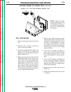
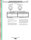
CONTROL CABLE CONTINUITY TEST
(continued)
TABLE F.6 CONTROL CABLE PIN AND LEAD DESIGNATIONS.
FIVE PIN AMPHENOL AT FIVE PIN AMPHENOL AT
POWER SOURCE END WIRE FEEDER/CONTROL BOX END
A A
B B
C C
D D
E E
Return to Section TOC Return to Section TOC Return to Section TOC Return to Section TOC
Return to Master TOC Return to Master TOC Return to Master TOC Return to Master TOC