


B-9
OPERATION
B-9
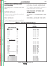
FEEDING ELECTRODE AND
BRAKE ADJUSTMENT
1. Turn the reel or spool until the free end of the
electrode is accessible.
2. While tightly holding the electrode, cut off the bent
end and straighten the first 6 in. (150 mm). Cut
off the first 1 in. (25 mm). (If the electrode is not
properly straightened, it may not feed or may jam
causing a “birdnest”.)
3. Insert the free end through the incoming guide.
4. Press the Cold Feed Switch while pushing the
electrode into the incoming wire guide.
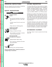
If feeding with the Gun Trigger, the electrode and
wire drive may be electrically “HOT”.
-----------------------------------------------------------
5. Feed the electrode through the gun.
6. Adjust the brake tension with the thumbscrew on
the spindle hub, until the reel turns freely but with
little or no overrun when wire feeding is stopped.
Do not overtighten.
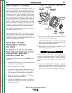
DRIVE ROLL KIT INSTALLATION
(KP1505-[])
1. Turn off welding power source.
2. Pull open pressure door to expose rolls and wire
guides.
3. Remove outer wire guide by turning knurled
thumb screws counterclockwise to unscrew them
from Feedplate.
4. Remove the drive rolls, if any are installed, by
pulling straight off the shaft. Remove the inner
guide.
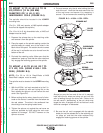
5. Insert the inner wire guide, groove side out, over
the two locating pins in the feedplate.
6. Install each drive roll by pushing over the shaft
until it butts up against the locating shoulder on
the drive roll shaft. (Do not exceed maximum wire
size rating of the wire drive).
7. Install the outer wire guide by sliding over the
locating pins and tightening in place.
8. Engage the upper drive rolls if they are in the
“open” position and close pressure door.
To set drive roll pressure, see
Drive Roll Pressure
Setting.
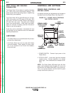
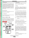
DRIVE ROLL PRESSURE
SETTING
The Power Feed 10 pressure is factory pre-set to
about position “2” as shown on the pressure indicator
on the front of the feedplate door. This is an approxi-
mate setting.
The optimum drive roll pressure varies with type of
wire, surface condition, lubrication, and hardness.
Too much pressure could cause “birdnesting”, but
too little pressure could cause wire feed slippage with
load and/or acceleration. The optimum drive roll set-
ting can be determined as follows:
1. Press end of gun against a solid object that is
electrically isolated from the welder output and
press the gun trigger for several seconds.
2. If the wire “birdnests”, jams, or breaks at the drive
roll, the drive roll pressure is too great. Back the
pressure setting out one turn, run new wire
through the gun, and repeat above steps.
3. If the only result is drive roll slippage, disengage
the gun, pull the gun cable forward about 6 in.
(150 mm). There should be a slight waviness in
the exposed wire. If there is no waviness, the
pressure is too low. Increase the pressure setting
one turn, reconnect the gun, tighten locking clamp
and repeat the above steps.
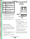
PROCEDURE FOR SETTING
ANGLE OF FEEDPLATE
1. Loosen the clamping collar screw using a 3/16 in.
Allen wrench. The clamping collar screw is
accessed from the bottom of the feedplate. It is
the screw which is perpendicular to the feeding
direction.
2. Rotate feedplate to the desired angle and tighten
clamping collar screw.
POWER WAVE 455/POWER FEED 10
WARNING
Return to Section TOC Return to Section TOC Return to Section TOC Return to Section TOC
Return to Master TOC Return to Master TOC Return to Master TOC Return to Master TOC