


F-69
TROUBLESHOOTING AND REPAIR
F-69
POWER WAVE 455/POWER FEED 10
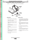
2. Tighten the two Allen type screws at
the bottom of the wire drive unit using
the 3/16 in. Allen wrench.
3. Attach lead #67 to the conductor block.
4. Carefully slide the drive motor into the
gear box assembly. Be sure to position
the motor leads so that they can be
properly connected.
5. Install the slot head screws that mount
the “top” of the drive motor to the gear
box.
6. Install the mounting screw located
inside the gearbox using the 5/16 in.
wrench.
7. Install the gear box inspection cover
and secure it with slot head screws.
8. Properly place insulation in the bottom
of the wire feeder case.
9. Place the entire gear box, drive motor
and wire drive assembly into the wire
feeder case, aligning the holes in the
glastic base insulator with the mounting
holes in the case.
10. Mount the gear box and drive motor
assembly to the wire feeder case using
the four mounting bolts, lock washers
and flat washers.
11. Connect the gas hose to the brass gun
connector block.
12. Connect drive motor leads #550 and
#551 to their quick disconnects.
13. Thread plug J4 and associated leads
through the vertical baffle and attach it
to the control board. Install cable ties
as necessary.
14. Install the wire feeder cover using the
3/8 in. nutdriver.
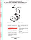
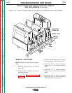
7. Using the needlenose pliers, discon-
nect the gas hose from the brass gun
connector block.
8. Using the 7/16 in. socket wrench,
remove the four mounting bolts, lock
washers, and flat washers from the
glastic base insulator.
9. Carefully slide and remove the entire
gear box, drive motor, and wire drive
assembly from the wire feeder
case. Note insulation placement for
reassembly.
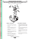
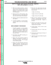
TO REMOVE THE DRIVE MOTOR
FROM THE GEAR BOX:
10. Using the slot head screwdriver,
remove the gear box inspection cover
nearest to the drive motor.
11. Using the 5/16 in. wrench, remove the
motor mounting screw located inside
the gear box.
12. Using the slot head screwdriver,
remove the two screws mounting the
“top” of the motor to the gear box.
13. Carefully remove the motor from the
gear box assembly. Note motor lead
placement for reassembly.
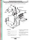
TO REMOVE THE WIRE DRIVE
ASSEMBLY FROM THE GEAR BOX:
14. Using the 3/16 in. Allen wrench, loosen
the two Allen type screws at the bottom
of the wire drive unit.
15. Remove lead #67 from the conductor
block.
16. Carefully slide and remove the wire
drive assembly from the gear box
assembly.
REPLACEMENT PROCEDURES
1. Carefully slide the wire drive assembly
and gear box together.
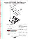
GEAR BOX AND DRIVE MOTOR REMOVAL AND REPLACEMENT
(continued)
Return to Section TOC Return to Section TOC Return to Section TOC Return to Section TOC
Return to Master TOC Return to Master TOC Return to Master TOC Return to Master TOC