


E-7
THEORY OF OPERATION
E-7
POWER WAVE 455/POWER FEED 10
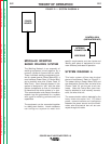
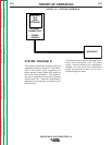
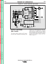
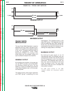
pulse width modulation (PWM) signal (See
Pulse Width Modulation
in this section) is
sent to the switch board IGBTs. In this
manner, the digitally controlled high-speed
welding waveform is created.
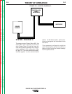
The control board also monitors the ther-
mostats, main transformer primary current,
and capacitor voltage, and activates either
the thermal light and/or the status light.
Dependent upon the fault situation, the con-
trol board will either disable or reduce
machine output, or de-energize the main
input contactor.
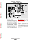
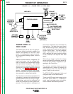
CONTROL BOARD
The control board performs the primary
interfacing functions to establish and main-
tain output control of the Power Wave 455.
Refer to Figure E.6. The control board
sends and receives digital command infor-
mation through the wire feeder receptacle
and or the RS232 connector. The software
that is contained within the control board
processes and compares these commands
with the voltage and current feedback infor-
mation it receives from the current sensor
and voltage sensing leads. The appropriate
FIGURE E.6 — CONTROL BOARD.
INPUT
CONTACTOR
INPUT
RECTIFIER
R
E
C
O
N
N
E
C
T
CONTROL BOARD
RIGHT
SWITCH
BOARD
LEFT
SWITCH
BOARD
MAIN
TRANSFORMER
CURRENT
SENSOR
CHOKE
OUTPUT
TERMINAL
OUTPUT
TERMINAL
POWER
BOARD
115VAC
RECEPTACLE
P
O
W
E
R
S
W
I
T
C
H
I
N
P
U
T
B
O
A
R
D
FAN
MOTOR
AUX.
TRANS.
AUX.
TRANS.
RECTIFIER
AUX.
RECONNECT
PRIMARY
CURRENT
SENSOR
WIRE FEEDER
RECEPTACLE
RS232
CONN.
THERMOSTATS
STATUS
LIGHT
THERMAL
LIGHT
CURRENT FEEDBACK
VOLTAGE FEEDBACK
65VDC
40VDC
CONTROL SIGNALS
PWM
DRIVE
CAPACITOR
VOLTAGE
FEEDBACK
CAPACITOR
VOLTAGE
FEEDBACK
PWM
DRIVE
VOLTAGE
SENSE
RECEPTACLE
#1
#2
S
W
I
T
C
H
Return to Section TOC Return to Section TOC Return to Section TOC Return to Section TOC
Return to Master TOC Return to Master TOC Return to Master TOC Return to Master TOC