


F-68
TROUBLESHOOTING AND REPAIR
F-68
POWER WAVE 455/POWER FEED 10
4. Thread plug J4 and associated leads
through the vertical baffle. Cut any
necessary cable ties.
5. Locate and disconnect the motor leads
(#551 and #550) at the quick connects.
Cut any necessary cable ties.
6. Using the Phillips head screwdriver,
remove the #67 lead from the conduc-
tor block.
PROCEDURE
1. Remove the input power to the wire
drive unit.
2. Using the 3/8 in. nutdriver, remove the
case cover.
3. Locate and remove plug J4 from the
control board. Refer to Figure F.20.
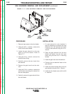
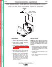
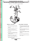
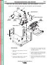
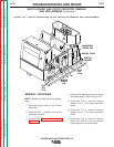
FIGURE F.20 — GEAR BOX AND DRIVE MOTOR REMOVAL AND REPLACEMENT.
DRIVE
MOTOR
#551
(BLACK)
#550
(WHITE)
GEAR BOX
GAS
FITTING
WIRE
DRIVE
ASSEMBLY
INSPECTION COVER
INSULATION
MOUNTING BOLT
J4
GEAR BOX AND DRIVE MOTOR REMOVAL AND REPLACEMENT
(continued)
Return to Section TOC Return to Section TOC Return to Section TOC Return to Section TOC
Return to Master TOC Return to Master TOC Return to Master TOC Return to Master TOC