


F-14
TROUBLESHOOTING AND REPAIR
F-14
POWER WAVE 455/POWER FEED 10
POWER FEED
Observe all Safety Guidelines detailed throughout this manual.
If for any reason you do not understand the test procedures or are unable to perform the tests/repairs safely, contact the Lincoln Electric
Service Department for technical troubleshooting assistance before you proceed. Call 216-383-2531 or 1-800-833-9353.
-----------------------------------------------------------------------------------------------------------------------------
CAUTION
PROBLEMS
(SYMPTOMS)
POSSIBLE AREAS OF
MISADJUSTMENT(S)
RECOMMENDED
COURSE OF ACTION
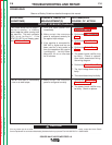
The purge switch on the wire drive
unit does not activate the gas sole-
noid, but gun trigger closure in the
MIG or Pulse modes does acitvate
the solenoid. The LEDs are steady
green on the power source,
Control Box and wire drive unit.
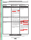
The COLD INCH/GAS PURGE
switch does not turn on the wire
drive motor but gun trigger closure
in the MIG or Pulse modes does
activate the wire drive motor. The
LEDs are steady green on the
power source, Control Box and
wire drive unit.
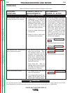
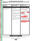
The voltmeter on the Control Box
does not function properly even
though the STATUS LEDS are
steady green.
1. Make certain the COLD
INCH/GAS PURGE switch is
operating properly.
2. Check for loose or faulty leads
between COLD INCH/GAS
PURGE switch and the wire
drive control board. See wiring
diagram.
1. Make certain the COLD
INCH/GAS PURGE switch is
operating properly.
2. Check for loose or faulty leads
between the COLD INCH/GAS
PURGE switch and the wire
drive control board. See wiring
diagram.
1. Make sure the DIP switches are
configured correctly for the weld-
ing polarity being used. See
Setting DIP Switches in the
Wire Drive
in the
Installation
section of this manual.
2. Check the #67 lead on the wire
drive unit. Make sure it is con-
nected to the motor gear box
and also the voltage sense PC
board.
3. Check the work sensing leads
on the Power Wave 455 power
source. Check leads #202
(Neg. output terminal) and #206
(Pos. output terminal). See
Power Wave 455 wiring dia-
gram. If external voltage sens-
ing is utilized, check the #21
lead between the 4-pin recepta-
cle on the front of the Power
Wave 455 and the workpiece.
1. If the COLD INCH/GAS PURGE
switch is operating correctly and
the associated leads are OK,
the wire drive control board may
be faulty.
1. If the COLD INCH/GAS PURGE
switch is operating correctly and
the associated leads are OK,
the wire drive control board may
be faulty.
1. Check leads #512B and #511
from plug J4 on the wire drive
control board to the voltage
sense PC board.
2. Perform the
Voltage Sense
Board Test.
3. The display board may be
faulty.
4. The wire drive control board
may be faulty.
5. The Control Box control board
may be faulty.
FUNCTION PROBLEMS (Continued)
Return to Section TOC Return to Section TOC Return to Section TOC Return to Section TOC
Return to Master TOC Return to Master TOC Return to Master TOC Return to Master TOC