


F-7
TROUBLESHOOTING AND REPAIR
F-7
POWER WAVE 455/POWER FEED 10
POWER WAVE
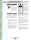
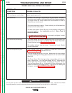
Observe all Safety Guidelines detailed throughout this manual.
If for any reason you do not understand the test procedures or are unable to perform the tests/repairs safely, contact the Lincoln Electric
Service Department for technical troubleshooting assistance before you proceed. Call 216-383-2531 or 1-800-833-9353.
-----------------------------------------------------------------------------------------------------------------------------
CAUTION
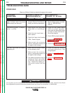
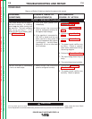
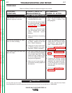
PROBLEMS
(SYMPTOMS)
POSSIBLE AREAS OF
MISADJUSTMENT(S)
RECOMMENDED
COURSE OF ACTION
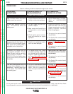
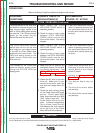
The thermal LED is lit. The
machine regularly overheats.
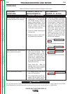
The Auxiliary Receptacle is “dead”.
The 115 VAC is missing.
The Power Wave 455 won’t pro-
duce full output.
1. Welding application may exceed
recommended duty cycle.
2. Dirt and dust may have clogged
the cooling channels inside the
machine. Refer to the
Mainte-
nance Section
of this manual.
3. Air intake and exhaust louvers
may be blocked due to inade-
quate clearance around
machine.
4. Make sure the fan is functioning
correctly.
1. Check the 10 amp circuit break-
er (CB2) located on the case
front. Reset if necessary.
2. Check the 10 amp circuit break-
er (CB3) located in the recon-
nect area. Reset if necessary.
1. The input voltage may be too
low, limiting the output capability
of the Power Wave 455. Make
certain the input voltage is prop-
er for the machine and recon-
nect panel configuration.
2. Make sure all three phases of
input power are being applied to
the machine.
1. One of the thermostats may be
faulty. Check or replace. See
wiring diagram.
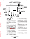
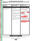
1. Check the receptacle and asso-
ciated wiring for loose or faulty
connections. See wiring dia-
gram. (Plugs P80 and P81)
2. Perform the
Auxiliary Transfor-
mer T2 Test.
1. Perform the
Output Rectifier
Test.
2. Perform the
Power Board Test.
3. Compare the display voltage
reading with an actual voltage
reading at the output terminals.
If the discrepancy is greater
than two volts the control board
may be faulty.
4. Perform the
Current Trans-
ducer Test.
OUTPUT PROBLEMS (Continued)
Return to Section TOC Return to Section TOC Return to Section TOC Return to Section TOC
Return to Master TOC Return to Master TOC Return to Master TOC Return to Master TOC