


TROUBLESHOOTING AND REPAIR
F-93
POWER WAVE 455/POWER FEED 10
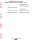
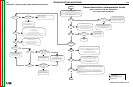
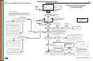
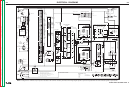
FLOWCHART - POWER SOURCE ERROR INTERPRETATION GUIDE
Code 12?
Start
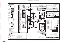
Codes 21,
22, or 23?
Code 36?
Code 31?
Codes 32, 33, 34,
and 35?
UI previously recognized by the system is no
longer communicating, but power appears to
be present at the UI. Check for intermittent
connections in the communication path
(pins A and B in the control cable, wires 541
and 542 in both the UI and FH).
UI Display and
Status light on?
UI previously recognized by the system is no
longer communicating, and no power appears to
be present at the UI. Check for intermittent
connections in the +40 VDC path (pins D and E
in the control cable, wires 540 and 500 in both
the UI and FH).
Weld Table Error is present.
Reload known good Weld Software.
Check the "All Modes" dipswitch in the UI, typically
SW2-8 (refer to dipswitch settings specified for the
software version loaded in the UI).
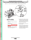
Thermal Error (generally accompanied by a thermal error light):
Check continuity of thermostat circuit. Thermostats are connected
in series, so open circuit reading indicates tripped thermostat or
faulty connection
Check operation of the cooling fan.
Check for excessive dirt build up in heatsink fins etc.
Perform Output
Rectifier Test
Replace Output
Rectifier Modules as
Required
The current transformer (CT)
feedback signal to the control
board is too high. Look for a
short in the transformer or
primary side of the machine.
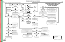
Perform the Switch
Board Test on both
sides.
Replace as Necessary.
Replacement board(s) must have
identical part number (including the
"dash number").
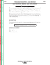
Code 32 and
33?
Code 34 and
35?
Both Switch boards are reporting an undervoltage error.
Check Input Voltage.
Perform the Input Board Test.
Check for proper reconnect position.
Look for faulty undervoltage connections from the Switch board(s) to the
Control board (+5VDC = normal, 0VDC = fault).
If the symptom is intermittent, Check the operation of the main contactor.
Both Switch boards are reporting an overvoltage error.
Check the Input Voltage.
Check for proper reconnect position.
Look for faulty overvoltage connections from the Switch
board(s) to the Control board
(+5VDC = normal, 0VDC = fault).
Machine configured
for 230V?
Invalid error combination. Check for
faulty overvoltage and undervoltage
connections from the Switch
board(s) to the Control board
(+5VDC = normal, 0VDC = fault).
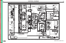
Code 32 and
34?
Code 33 and
35?
Perform the Switch Board
Test on Side "A" (left side
facing the front of
machine)
Perform the Switch Board
Test on Side "B" (right
side facing the front of
machine)
Replace the Switch Board
Replacement board(s) must have
identical part number (including
the "dash number").
Replace the Switch
BoardReplacement board(s)
must have identical part number
(including the "dash number").
Check main capacitor for a short circuit
condition.
Check for faulty overvoltacge and
undervoltage connections from the Switch
board(s) to the Control board
(+5VDC = normal, 0VDC = fault).
N
Y
Y
Y
N
Y
Y Pass
Fail
Y
Fail
N
Y
Y
N
N
Y
N
Y
Fail
Pass
N
Y Pass
Fail
N
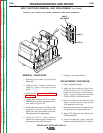
Any of the following
codes:
32, 33, 34, or 35?
Code 37?
Soft Start failure.
Generally accompanied by under and over voltage errors
(32-35), because the system is unable to charge the
main capacitors to an acceptable voltage level.
Follow the branch for under and over voltage errors
(32-35) to test the Input Bd., Switch Bd., and main
contactor operation.
Finish
Y
N
N
N
N
N
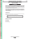
Power Source Error Interpretation Guide
Error codes that contain three or four digits are defined as fatal errors. These codes
generally indicate internal errors on the PS Control Board. If cycling the input power on
the machine does not clear the error, try reloading the operating system. If this fails,
replace the control board.
EXCEPTION:
Reoccuring fatal errorscan sometimes be caused by overloading the system. As an
example this could occur in earlier versions of PS software when rapidly changing from
one head to the another on a multi-head system (i.e. PF10x2). Adding a minimum (0.1
seconds) of preflow time to each head or upgrading the operating system shoudl
generally solve the problem.
Other Codes?
N
Y
(Semi Automatic PW-455, PW455/STT)
If the PS Status light is flashing any combination of red and green,
errors are present in the PW-455.
Error Code interpretation through the Status light is detailed in the
Service Manual. Individual code digits are flashed in red with a long
pause between digits. If more than one code is present, the codes
will be se
p
arated b
y
a
g
reen li
g
ht.
Key:
PS = Power Source
UI = User Interface (Control
Box)
FH = Feed Head
Perform the Contactor Test.
Perform Input Board Test.
Perform the Input Rectifier Test.
Pass
(For Codes 10555 and Below)
F-93
Return to Section TOC Return to Section TOC Return to Section TOC Return to Section TOC
Return to Master TOC Return to Master TOC Return to Master TOC Return to Master TOC