


A-15
INSTALLATION
POWER WAVE 455/POWER FEED 10
A-15
GUN AND CABLE ASSEMBLIES
GUN AND CABLE ASSEMBLIES WITH
STANDARD CONNECTION
The Power Feed 10 wire feeder is equipped with a
factory installed K1500-2 gun connection kit. This kit
is for guns having a Tweco™ #2-#4 connector. The
Power Feed 10 has been designed to make connect-
ing a variety of guns easily and inexpensively with the
K1500 series of gun connection kits. Gun trigger and
dual procedure lead connections connect to the single
five pin receptacle on the front of the feed head box.
See
Gun Adapters
in
Accessories
section.
GENERAL GUN CONNECTION GUIDELINES
The instructions supplied with the gun and K1500
series gun adapter should be followed when
installing and configuring a gun. What follows are
some general guidelines that are not intended to
cover all guns.
a. Check that the drive rolls and guide tubes
are proper for the electrode size and type
being used. If not, change them per drive
roll installation instructions in the
Operation
section.
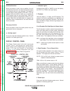
b. Lay the cable out straight. Insert the connec-
tor on the welding conductor cable into the
brass conductor block on the front of the wire
drive head. Make sure it is all the way in and
tighten the hand clamp. Keep this connec-
tion clean and bright. Connect the trigger
control cable polarized plug into the mating
five cavity receptacle on the front of the wire
drive unit.
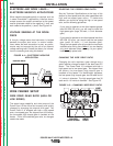
NOTE: For Fast-Mate and European connector style
guns, connect gun to gun connector making sure all
pins and gas tube line up with appropriate holes in
connector. Tighten gun by turning large nut on gun
clockwise.
c. For GMA gun cables with separate gas fit-
tings, connect the 3/16 in. I.D. gas hose
from the wire drive unit to the gun cable
barbed fitting.
d. For water cooled guns, refer to the instruc-
tions supplied with the kit.
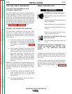
GMAW SHIELDING GAS
CYLINDER may explode if damaged.
• Keep cylinder upright and chained to
support.
• Keep cylinder away from areas where it
may be damaged.
• Never lift welder with cylinder attached.
• Never allow welding electrode to touch
cylinder.
• Keep cylinder away from welding or
other live electrical circuits.
BUILDUP OF SHIELDING GAS may
harm health or kill.
• Shut off shielding gas supply when not
in use.
SEE AMERICAN NATIONAL STANDARD Z-49.1,
“SAFETY IN WELDING AND CUTTING” PUB-
LISHED BY THE AMERICAN WELDING
SOCIETY.
-----------------------------------------------------------
Customer must provide a cylinder of shielding gas, a
pressure regulator, a flow control valve, and a hose
from the flow valve to the gas inlet fitting of the wire
drive unit.
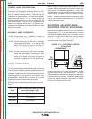
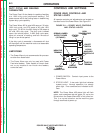
Connect a supply hose from the gas cylinder flow
valve outlet to the 5/8-18 female inert gas fitting on
the back panel of the wire drive or, if used, on the
inlet of the Gas Guard Regulator. See
Accessories
section.
WARNING
Return to Section TOC Return to Section TOC Return to Section TOC Return to Section TOC
Return to Master TOC Return to Master TOC Return to Master TOC Return to Master TOC