


F-27
TROUBLESHOOTING AND REPAIR
F-27
POWER WAVE 455/POWER FEED 10
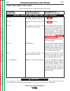
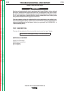
8. Reconnect leads 19C and 19D to the
reconnect switches. Ensure that the
leads are installed in the same location
they were removed from.
9. Install the right and left case sides
using the 3/8 in. nutdriver.
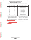
6. If any test fails replace both switch
boards. See
Switch Board Removal
and Replacement.
7. If the switch board resistance tests are
OK, check the molex pin connections
and associated wiring from the switch
boards to the control board. See wiring
diagram.
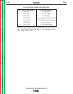
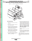
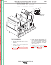
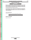
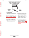
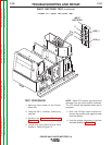
FIGURE F.3 — SWITCH BOARD TEST POINTS.
SWITCH
BOARD
-20+19
11/12
OR
15/16
13/14
OR
17/18
SWITCH BOARD TEST
(continued)
APPLY POSITIVE TEST APPLY NEGATIVE TEST NORMAL
PROBE TO TERMINAL PROBE TO TERMINAL RESISTANCE READING
+19 11/12 OR 15/16 Greater than 1000 ohms
+19 13/14 OR 17/18 Greater than 1000 ohms
11/12 OR 15/16 - 20 Greater than 1000 ohms
13/14 OR 17/18 - 20 Greater than 1000 ohms
- 20 11/12 OR 15/16 Less than 100 ohms
- 20 13/14 OR 17/18 Less than 100 ohms
11/12 OR 15/16 +19 Less than 100 ohms
13/14 OR 17/18 +19 Less than 100 ohms
TABLE F.1 — SWITCH BOARD RESISTANCE TEST.
Return to Section TOC Return to Section TOC Return to Section TOC Return to Section TOC
Return to Master TOC Return to Master TOC Return to Master TOC Return to Master TOC