


F-26
TROUBLESHOOTING AND REPAIR
F-26
POWER WAVE 455/POWER FEED 10
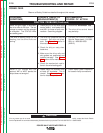
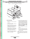
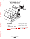
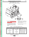
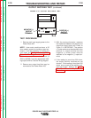
4. Locate label and remove leads 19C
and 19D from the reconnect switches
with the 3/8 in. wrench. Note lead
placement for reassembly. Clear leads.
Refer to Figure F.2.
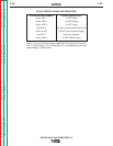
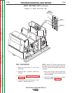
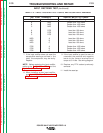
5. Using the Analog ohmmeter, perform
the resistance tests detailed in Table
F.1. Refer to Figure F.3 for the test
points.
TEST PROCEDURE
1. Remove input power to the Power
Wave 455.
2. Using the 3/8 in. nutdriver, remove the
case top and sides.
3. Perform the
Capacitor Discharge
Procedure.
FIGURE F.2 — RECONNECT SWITCHES.
19C
19D
RECONNECT
SWITCHES
SWITCH BOARD TEST
(continued)
Return to Section TOC Return to Section TOC Return to Section TOC Return to Section TOC
Return to Master TOC Return to Master TOC Return to Master TOC Return to Master TOC