


F-48
TROUBLESHOOTING AND REPAIR
F-48
POWER WAVE 455/POWER FEED 10
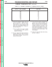
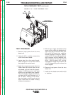
7. Check for the correct DC supply volt-
ages to the current transducer at plug
P90.
A. Pin 1 (lead 212+) to pin 4 (lead
216-) should read +15 VDC.
B. Pin 2 (lead 213-) to pin 4 (lead
216+) should read -15 VDC.
8. If either of the supply voltages are low
or missing, check the associated leads
between the current transducer and the
control board. If the leads are OK and
the DC supply voltages are not present,
the control board may be faulty.
TEST PROCEDURE
1. Remove input power to the Power
Wave 455.
2. Using the 3/8 in. nutdriver remove the
right side case cover.
3. Perform the
Capacitor Discharge
Procedure.
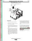
4. Locate the current transducer at the
lower right front of the machine.
5. Apply the correct input power to the
Power Wave 455.
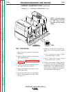
6. Locate plug P90 at the current trans-
ducer. Do not remove the plug. Refer
to Figure F.11.
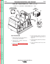
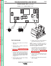
FIGURE F.11 — CURRENT TRANSDUCER TEST.
4321
P90
CURRENT
TRANSDUCER
CURRENT TRANSDUCER TEST
(continued)
Return to Section TOC Return to Section TOC Return to Section TOC Return to Section TOC
Return to Master TOC Return to Master TOC Return to Master TOC Return to Master TOC
NOTE: On later codes
the transducer is located
on left side of the
machine near the output
choke.