


A-8
INSTALLATION
POWER WAVE 455/POWER FEED 10
A-8
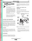
CONTROL CABLE SPECIFICATIONS
The cable is a five copper conductor cable in a SO-
type rubber jacket. There is one 20 gauge twisted
pair for network communications. This pair has an
impedance of approximately 120 ohms and a propa-
gation delay per foot of < 2.1 ns. There are two 12
gauge conductors that are used to supply the 40
VDC to the network. The fifth wire is 18 gauge and is
used as an electrode sense lead. It is typically con-
nected to the feed plate on the feed head when that
feed head is active.
AVAILABLE CABLE ASSEMBLIES
K1543 Control cable only. Available in lengths of
8, 16, 25, 50 and 100 feet.
K1544 Control cable and a 3/0 (85 mm
2
) electrode
cable with stud terminal. It is rated at 600
amps, 60% duty cycle and is available in
lengths of 8, 16, 25, and 50 feet.
K1545 Control cable and a 3/0 (85 mm
2
) electrode
cable with Twist-Mate™ connector on one
end and a stud terminal on the other. It is
rated at 500 amps, 60% duty cycle and is
available in lengths of 8, 16, 25, and 50 feet.
CABLE CONNECTIONS
To avoid interference problems with other equipment
and to achieve the best possible operation, route all
cables directly to the work or wire feeder. Avoid
excessive lengths, bundle the electrode and ground
cables together where practical, and do not coil
excess cable. Be sure the connection to the work
makes tight metal-to-metal electrical contact.
Minimum work and electrode cables sizes are as fol-
lows:
When using an inverter type power source, use the
largest welding (electrode and ground) cables that
are practical. At least 2/0 copper wire — even if the
average output current would not normally require it.
When pulsing, the pulse current can reach very high
levels. Voltage drops can become excessive, lead-
ing to poor welding characteristics, if undersized
welding cables are used.
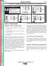
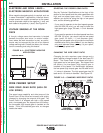
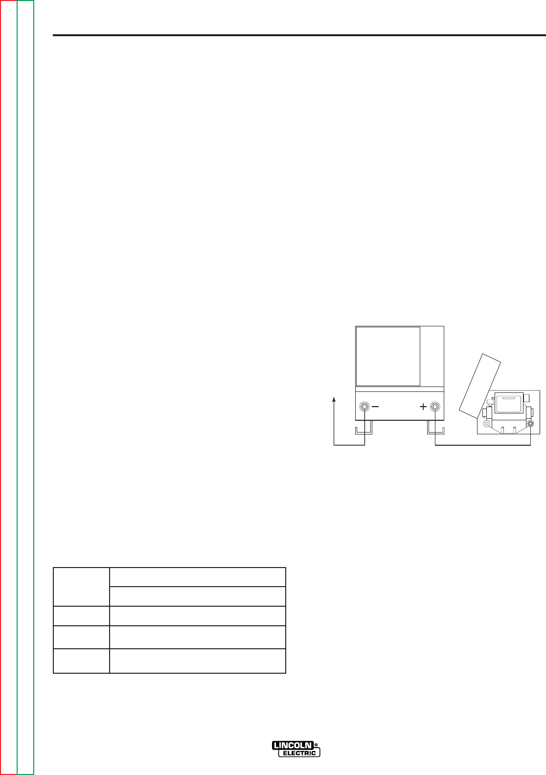
ELECTRODE AND WORK LEADS —
ELECTRODE POSITIVE APPLICATIONS
Most welding applications run with the electrode
being positive (+). For those applications, connect
the electrode cable between the wire feeder and the
positive (+) output stud on the power source (located
beneath the spring loaded output cover near the bot-
tom of the case front). See Figure A.3.
FIGURE A.3 — ELECTRODE POSITIVE
APPLICATION.
A work lead must be run from the negative (-) power
source output stud to the work piece. The work
piece connection must be firm and secure, especially
if pulse welding is planned. Excessive voltage drops
at the work piece connection often result in unsatis-
factory pulse welding performance.
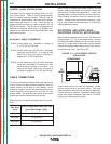
Minimum Copper Work Cable Size, AWG
Up to 100 ft Length (30m)
Current
60% Duty
Cycle
400 Amps
500 Amps
600 Amps
2/0 (67 mm
2
)
3/0 (85 mm
2
)
3/0 (85 mm
2
)
POWER WAVE
WIRE
FEEDER
TO
WORK
Return to Section TOC Return to Section TOC Return to Section TOC Return to Section TOC
Return to Master TOC Return to Master TOC Return to Master TOC Return to Master TOC