


C-9
ACCESSORIES
C-9
POWER WAVE 455/POWER FEED 10
4. Position the new door between the panel holes
and re-install the rod so the screw holes can be
accessed.
5. Replace the two screws and tighten.
6. Swing the door into the up position. A lock may
be installed through the side holes for security
purposes.
K1555-1 INSULATED LIFT BAIL
For applications where an insulated lift bail is
required. This kit provides an easily installed, heavy
duty insulated lift eye that mounts to the wire reel
stand mast. See the instructions provided with the kit
for installation.
DESCRIPTION AND INSTALLATION OF
OPTIONAL CONTROL BOX PANELS
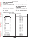
K1542-5 DUAL PROCEDURE PANEL
The Dual Procedure Panel provides a fixed large tog-
gle switch or the use of a gun switch for the selection
of either of two procedures. The upper position of the
switch selects PROCEDURE A, while the lower
selects PROCEDURE B. The middle position selects
the GUN switch, in which case the procedure is
determined by the position of the switch located at
the gun.
NOTE: Due to the nature of fixed position switches,
this option does not allow the indication of a remotely
selected procedure. When in the gun mode there is
no provision to indicate, at the Control Box, which
procedure has been remotely selected (at the gun).
Installation is as follows:
1. Turn off power.
2. Remove the two screws from the front of the
blank option panel at the location you choose to
install your new option, (middle or top), of the
Control Box cabinet. Save the screws, discard
the old panel or save for future use.
3. Tilt the new option panel away from the front
opening of the Control Box cabinet. Plug the
electrical connector into the proper connector on
the right side of the main printed circuit board
(10 pin). Make sure the connector latches in
place.
4. Position the new panel, taking care not to dam-
age the switch connections on the back.
5. Align the screw holes, replace the two screws
and tighten.
K1542-6 M PANEL
The M Panel provides a large toggle switch selection
of three power source modes. The upper position
selects the generic CV/MIG mode from the power
source, the middle position selects the CV/FLUX
CORED mode, and the lower position selects the
CC/STICK/GOUGE mode. Arc control is accom-
plished through the use of the ARC CONTROL
potentiometer. The arc control value is actually a trim
with zero being the nominal and the scale ranging
from (-10) to (+10). Preflow, postflow, and spot time
default to zero or off. Run in defaults to the minimum
value, or weld speed depending on the position of its
associated DIP switch. See
Installation
section for
DIP switch settings. Burnback defaults to the on
board trimmer adjustment.
NOTE: Due to the nature of fixed position switches,
potentiometers, and default values, this option does
not allow the mode, arc control, timers, or burnback
values to be included in dual procedure or memory
information. They are overridden by the fixed values.
CC/STICK/GOUGE Mode
Selecting the CC/STICK/GOUGE mode on this panel
automatically energizes the output terminals on the
power source, making the power source immediately
ready to weld. In the CC modes, the output current is
set by the AMPS control, and the VOLTS/TRIM
adjustment has no effect in this mode. In this mode,
the ARC CONTROL adjusts the arc force. Increasing
the ARC CONTROL setting increases the arc force,
making the arc more harsh but less likely to stick.
Decreasing the ARC CONTROL setting decreases
the arc force, making the arc softer and smoother.
Return to Section TOC Return to Section TOC Return to Section TOC Return to Section TOC
Return to Master TOC Return to Master TOC Return to Master TOC Return to Master TOC