


A-10
INSTALLATION
POWER WAVE 455/POWER FEED 10
A-10
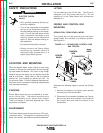
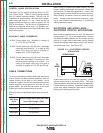
RATIO CHANGE PROCEDURE
1. Pull open the pressure door.
2. Remove the Phillips head screw retaining the
pinion gear to be changed and remove the gear.
If the gear is not easily accessible or difficult to
remove, remove the feed plate from the gearbox.
To remove feed plate:
a. Loosen the clamping collar screw using a
3/16 in. Allen wrench. The clamping collar
screw is accessed from the bottom of the
feed plate. It is the screw which is perpendic-
ular to the feeding direction.
b. Loosen the retaining screw, which is also
accessed from bottom of feeder, using a
3/16 in. Allen wrench. Continue to loosen the
screw until the feed plate can be easily
pulled off of the wire feeder.
3. Loosen, but do not remove, the screw on the
lower right face of the feed plate with a 3/16 in.
Allen wrench.
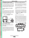
4. Remove the screw on the left face of the feed
plate. If changing from high speed (larger gear)
to low speed (smaller gear), line the upper hole
on the left face of the feed plate with the threads
on the clamping collar. Line the lower hole with
the threads to install larger gear for high speed
feeder. If feed plate does not rotate to allow
holes to line up, further loosen the screw on right
face of feed plate.
5. Remove the small gear from the output shaft.
Lightly cover the output shaft with engine oil or
equivalent. Install gear onto output shaft and
secure with flat washer, lock washer, and Phillips
head screw which were previously removed.
6. Tighten the screw on lower right face of feed
plate.
7. Re-attach feed plate to wire feeder if removed in
Step 2.
8. Feed plate will be rotated out-of-position due to
the gear change. Adjust the angle of the feed
plate by loosening the clamping collar screw
(Step 2a) and pivoting feed head.
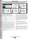
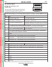
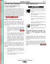
9. Set the High/Low switch code on Feed Head PC
board as follows:
a. Power down the Power Feed by turning off its
campanion Power Wave power source. For
maximum safety, disconnect the control cable
from the Power Feed.
b. Remove the cover from the back of the feed
head (2 screws).
c. Locate the 8-position DIP switch near the top
edge of the PC board, centered left to right.
The setting will be made on the right most
switch, S8.
d. Using a pencil or other small object, slide the
switch down, to the “0” position, when the low
speed gear is installed. Conversely, slide the
switch up, to the “1” position, when the high
speed gear is installed. Refer to Figure A.6.
e. Replace the cover and screws. The PC board
will “read” the switch at power up, automati-
cally adjusting all control parameters for the
speed range selected.
Return to Section TOC Return to Section TOC Return to Section TOC Return to Section TOC
Return to Master TOC Return to Master TOC Return to Master TOC Return to Master TOC