


F-8
TROUBLESHOOTING AND REPAIR
F-8
POWER WAVE 455/POWER FEED 10
POWER WAVE
Observe all Safety Guidelines detailed throughout this manual.
If for any reason you do not understand the test procedures or are unable to perform the tests/repairs safely, contact the Lincoln Electric
Service Department for technical troubleshooting assistance before you proceed. Call 216-383-2531 or 1-800-833-9353.
-----------------------------------------------------------------------------------------------------------------------------
CAUTION
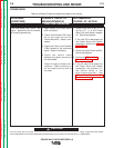
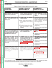
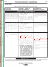
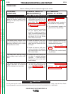
PROBLEMS
(SYMPTOMS)
POSSIBLE AREAS OF
MISADJUSTMENT(S)
RECOMMENDED
COURSE OF ACTION
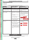
For no apparent reason, the weld-
ing characteristics have changed.
The machine often “noodle welds”
with a particular procedure.
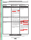
The arc burns back to the tip.
1. Check for proper wire feed
speed setting. In the MIG/MAG
and FCAW modes, check for
proper voltage settings. In the
MIG/MAG pulse modes, check
the arc length trim setting.
These controls are on the
Control Box (user interface).
2. Check for proper shielding gas
and gas flow.
3. Check for loose or faulty weld-
ing cables and connections.
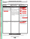
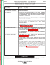
1. The machine may be trying to
deliver too much power. When
the average output current
exceeds a maximum limit, the
machine will “phase back” to
protect itself. Adjust the proce-
dure or reduce the load to lower
the current draw from the Power
Wave 455 machine.
Power Wave 455 - When the
average output current exceeds
570 amps, the output current is
phased back to 100 amps.
1. The voltage settings may be too
high for the procedure.
2. The voltage sensing lead or con-
nection may be faulty. See the
Power Feed 10 Wiring Diagram
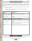
1. If zero arc voltage is displayed
on the Control Box while weld-
ing, the voltage sense leads
may be broken. Check lead #67
at the wire drive. See wiring
diagram. Also check leads
#202 (Neg. output terminal) and
#206 (Pos. output terminal).
See Power Wave 455 wiring
diagram. If external voltage
sensing is utilized, check the
#21 lead between the 4-pin
receptacle on the Power Wave
455 and the workpeice.
2. Perform the
Output Rectifier
Test.
3. The control board may be faulty.
4. Perform the
Current Trans-
ducer Test.
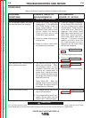
1. Perform the
Current Trans-
ducer Test.
2. The control board may be faulty.
1. Perform the
Voltage Sense PC
Board Test.
WELDING PROBLEMS
Return to Section TOC Return to Section TOC Return to Section TOC Return to Section TOC
Return to Master TOC Return to Master TOC Return to Master TOC Return to Master TOC