


F-80
TROUBLESHOOTING AND REPAIR
F-80
POWER WAVE 455/POWER FEED 10
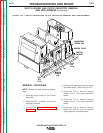
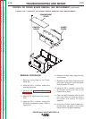
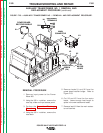
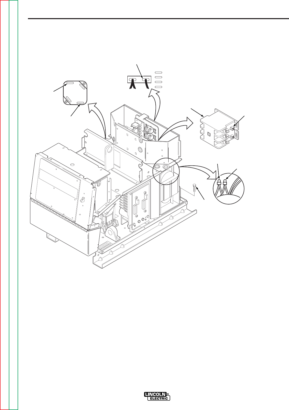
5. Remove leads X1 and X2 from the
power board rectifier bridge. Refer to
Figure F.23.
6. Cut X3 and X5 from the fan motor
leads. Leave enough lead length to
splice in the new transformer leads.
7. Remove lead X4 from the main contac-
tor coil terminal.
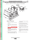
REMOVAL PROCEDURE
1. Remove input power to the Power
Wave 455.
2. Using the 3/8 in. nutdriver, remove the
case top, sides and input access panel.
3. Perform the
Capacitor Discharge
Procedure.
4. Using the 3/8 in. nutdriver, remove the
case back.
FIGURE F.23 — AUXILIARY TRANSFORMER NO. 1 REMOVAL AND REPLACEMENT PROCEDURE.
POWER BOARD
RECTIFIER BRIDGE
X1
X2
X3
X5
MOUNTING
SCREW
(2X)
FAN
MOTOR
LEADS
RECONNECT
TERMINALS
CB4
H1
H2
H3
H4
H5
MAIN
CONNECTOR
X4
AUXILIARY TRANSFORMER NO. 1 REMOVAL AND
REPLACEMENT PROCEDURE
(continued)
Return to Section TOC Return to Section TOC Return to Section TOC Return to Section TOC
Return to Master TOC Return to Master TOC Return to Master TOC Return to Master TOC