


3. HIGH TEMPERATURE LIGHT (thermal overload):
A yellow light that comes on when an over tem-
perature situation occurs. Output is disabled until
the machine cools down. When cool, the light
goes out and output is enabled.
4. 10 AMP WIRE FEEDER CIRCUIT BREAKER:
Protects 40 volt DC wire feeder power supply.
5. 10 AMP AUXILIARY POWER CIRCUIT BREAK-
ER: Protects 115 volt AC receptacle.
POWER FEED CONTROLS
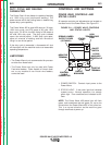
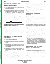
1. 2-STEP/4-STEP SWITCH OPERATION
The Power Feed head unit has a 2-Step/4-Step
switch shown in Figure B.2. This switch has no
effect in CC modes of operation such as stick weld-
ing. When in the 2-step position, the gun trigger func-
tions as follows:
2-Step Operation:
1. Closing the gun trigger initiates gas preflow time
followed by run in speed and strike voltage until
welding current is established.
2. Opening the gun trigger during a weld stops wire
feed and initiates burnback time, followed by gas
postflow time.
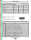
Meaning
System OK. Power source communicating
normally with wire feeder and its
components.
Nothing connected to Wire Feeder
Receptacle.
Recoverable system fault. See
Troubleshooting Section.
Non-recoverable system fault. Must turn
power source off, find source of error, and
turn power back on to reset. See
Troubleshooting Section.
See Troubleshooting Section.
B-4
OPERATION
B-4
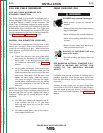
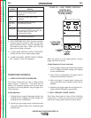
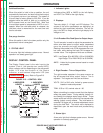
FIGURE B.2 — WIRE FEEDER CONTROLS.
When the switch is in the 4-step position, the gun
trigger functions as follows:
4-Step Operation (Current interlock):
1. Closing trigger initiates gas preflow time followed
by run in speed and strike voltage until welding
current is established.
2. Once current is established, the trigger may be
released and welding will continue.
3. When the trigger is closed again, welding will
continue but the current interlock function will be
disabled.
4. Releasing the trigger stops the wire feed and ini-
tiates burnback followed by gas postflow.
2. COLD FEED/GAS PURGE SWITCH
The Power Feed head unit has a Cold Feed/Gas
Purge switch. When left untouched, this switch
returns to a center position where no action results.
POWER WAVE 455/POWER FEED 10
Light
Condition
Steady Green
Blinking
Green
Alternating
Green and
Red
Steady Red
Blinking Red
COLDFEED
STATUS
4-STEP
2-STEP
CONTROL BOX
(SHOWN ATTACHED
TO WIRE FEEDER)
2. COLD FEED/
GAS PURGE
SWITCH
3. STATUS
LIGHT
1. 2-STEP/
4-STEP
SWITCH
Return to Section TOC Return to Section TOC Return to Section TOC Return to Section TOC
Return to Master TOC Return to Master TOC Return to Master TOC Return to Master TOC