


E-5
THEORY OF OPERATION
E-5
POWER WAVE 455/POWER FEED 10
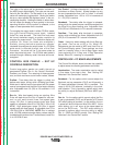
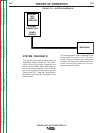
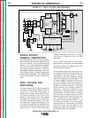
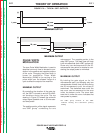
voltage developed by the No. 2 auxiliary
transformer is applied to the 115 VAC
receptacle.
The 65 VDC produced from the power
board rectifier is utilized by the power board
to provide various DC voltages for the con-
trol board and wire feeder.
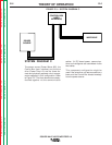
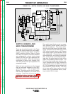
The two phases which are connected to the
input board, through the power switch, are
connected to the input rectifier. During
precharge or “soft start” these two phases
are current limited by the input board. This
AC input voltage is rectified, and the resul-
tant DC voltage is applied through the
reconnect switches to the input capacitors
located on the switch boards. The control
board monitors the voltage across the
capacitors. When the capacitors have
charged to an acceptable level, the control
board signals the input board to energize
the main input contactor making all three
phases of input power, without current limit-
ing, available to the input capacitors. At
this point, the Power Wave 455 is in the
“Run Mode” of operation. If the capacitors
become under or overvoltage, the control
board will signal the input board to de-
energize the main input contactor, and the
Power Wave 455 will be disabled.
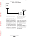
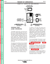
POWER SOURCE
GENERAL DESCRIPTION
The Power Wave 455 is an inverter based
welding power source that is designed to be
part of a modular, multi-process welding
system. It is a high performance, digitally
controlled inverter capable of complex,
high-speed waveform control. With the
appropriate modular components it can sup-
port constant current, constant voltage and
pulse welding processes. The output rating
is 450 amps at 38 volts with a 100% duty
cycle.
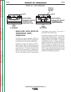
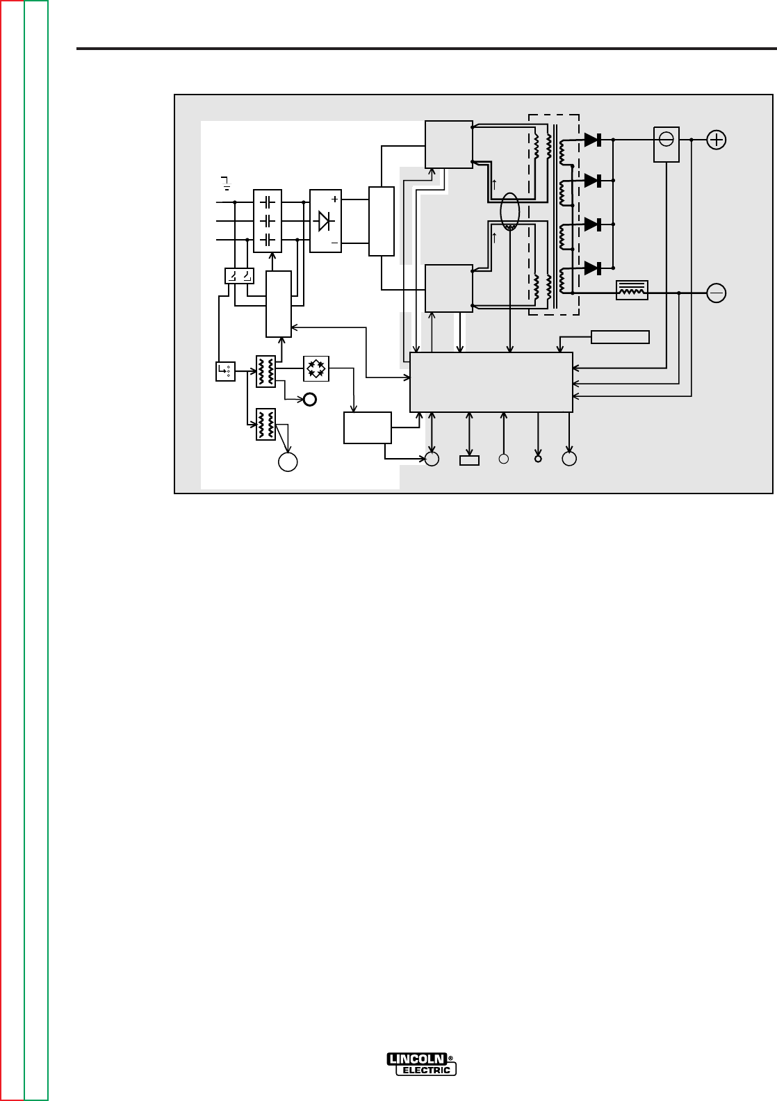
INPUT VOLTAGE AND
PRECHARGE
The Power Wave 455 can be connected for
a variety of three phase voltages. Refer to
Figure E.4. The initial input power is
applied to the Power Wave 455 through a
line switch located on the front of the
machine. Two phases of the three-phase
input power is applied to the input board
and both auxiliary transformers. The vari-
ous secondary voltages developed by the
#1 auxiliary transformer are applied to the
input board, the power board rectifier and
the fan motor. The 115 VAC secondary
FIGURE E.4 — INPUT VOLTAGE AND RECHARGE.
INPUT
CONTACTOR
INPUT
RECTIFIER
R
E
C
O
N
N
E
C
T
CONTROL BOARD
RIGHT
SWITCH
BOARD
LEFT
SWITCH
BOARD
MAIN
TRANSFORMER
CURRENT
SENSOR
CHOKE
OUTPUT
TERMINAL
OUTPUT
TERMINAL
POWER
BOARD
115VAC
RECEPTACLE
P
O
W
E
R
S
W
I
T
C
H
I
N
P
U
T
B
O
A
R
D
FAN
MOTOR
AUX.
TRANS.
AUX.
TRANS.
RECTIFIER
AUX.
RECONNECT
PRIMARY
CURRENT
SENSOR
WIRE FEEDER
RECEPTACLE
RS232
CONN.
THERMOSTATS
STATUS
LIGHT
THERMAL
LIGHT
CURRENT FEEDBACK
VOLTAGE FEEDBACK
65VDC
40VDC
CONTROL SIGNALS
PWM
CAPACITOR
VOLTAGE
FEEDBACK
PWM
DRIVE
VOLTAGE
SENSE
RECEPTACLE
#1
#2
S
W
I
T
C
H
DRIVE
FEEDBACK
VOLTAGE
CAPACITOR
Return to Section TOC Return to Section TOC Return to Section TOC Return to Section TOC
Return to Master TOC Return to Master TOC Return to Master TOC Return to Master TOC