


A-14
INSTALLATION
POWER WAVE 455/POWER FEED 10
A-14
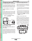
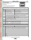
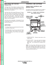
SETTING DIP SWITCHES IN THE WIRE
DRIVE
There is one DIP switch bank on the control board of
the wire drive. It’s labeled S1 and is located and ori-
ented as shown in Figure A.4.
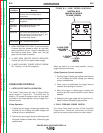
FIGURE A.4
S1 DIP Switch on Wire Drive Control Board (For software version S24029-All & S24467)
Switch Off On
1 Network Group ID, MSB (Assigns Wire Drive to a specific group)
2 Network Group ID, LSB (Assigns Wire Drive to a specific group )
3 Network Feed Head ID, MSB (Assigns feed head number to wire drive)
4 Network Feed Head ID (Assigns feed head number to wire drive)
5 Network Feed Head ID, LSB (Assigns feed head number to wire drive)
6 Spare
7 Electrode Sense Polarity = Positive Electrode Sense Polarity = Negative
Switch position must match polarity of weld cable attached to feed plate.
8 Gear Box Ratio = Low Gear Box Ratio = High
Switch position must match actual gear box ratio of wire drive.
Note: the factory shipped settings for all of the S1 switches is “OFF”.
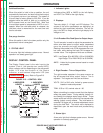
S1
ON
1 2 3 4 5 6 7 8
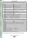
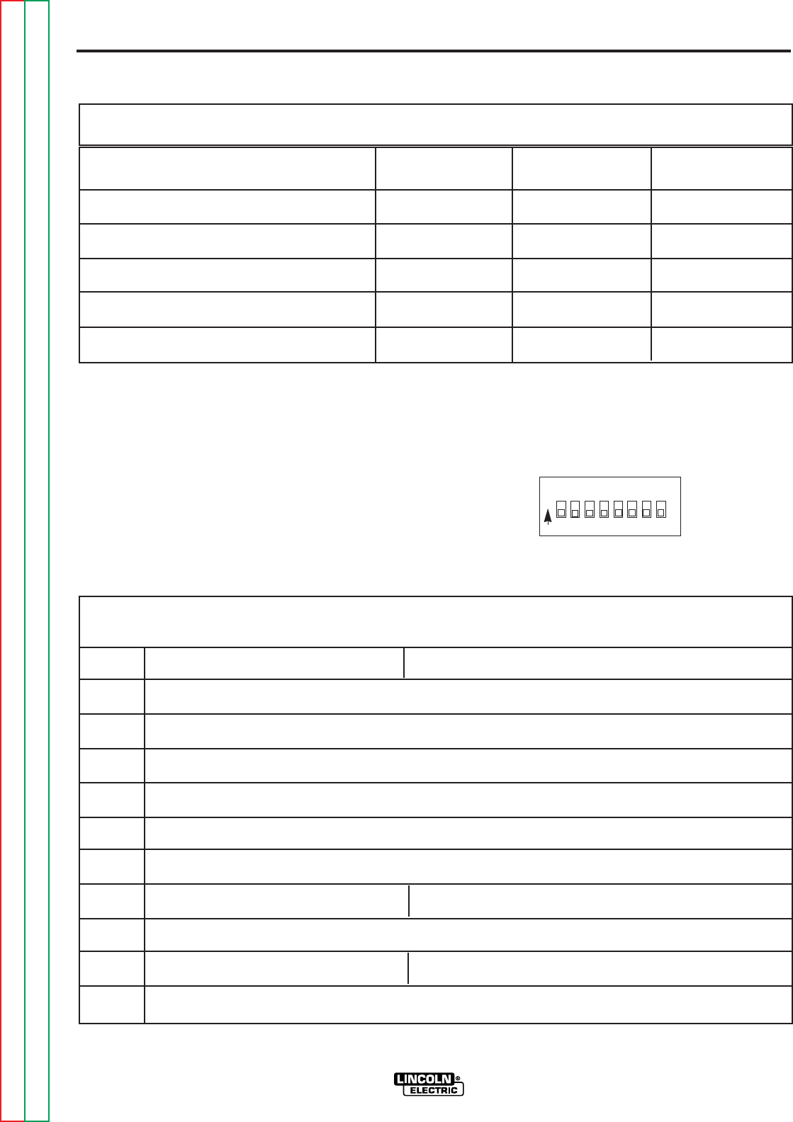
DIP SWITCH 6 DIP SWITCH 7 DIP SWITCH 8
Acceleration 1 (slow) Off Off On
Acceleration 2 Off On Off
Acceleration 3 Off On On
Acceleration 4 On Off Off
Acceleration 5 (fast ) (factory setting) Off Off Off
Setting Wire Drive Acceleration Rate Using (All software versions)
DIP Switch S1 on the Control Box Motherboard
Return to Section TOC Return to Section TOC Return to Section TOC Return to Section TOC
Return to Master TOC Return to Master TOC Return to Master TOC Return to Master TOC