


F-72
TROUBLESHOOTING AND REPAIR
F-72
POWER WAVE 455/POWER FEED 10
4. Remove the molex plug from the top of
the switch board. Refer to Figure F.21.
5. Using the 7/16 in. wrench, remove
leads 11/12 or 15/16 from the switch
board.
6. Using the 7/16 in. wrench, remove
leads 13/14 or 17/18 from the switch
board.
7. Using the 7/16 in. wrench, remove
leads 19+ and 20- from the switch
board capacitor connection bolts.
REMOVAL PROCEDURE
NOTE: Observe all static electricity precau-
tions.
1. Remove input power to the Power
Wave 455.
2. Using the 3/8 in. nutdriver, remove the
case top and sides.
3. Perform the
Capacitor Discharge
Procedure.
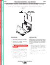
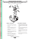
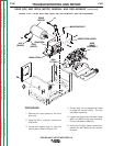
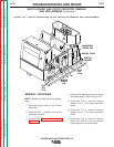
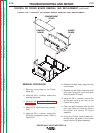
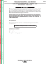
FIGURE F.21 — SWITCH BOARD AND FILTER CAPACITOR REMOVAL AND REPLACEMENT.
MOUNTING
SCREW (4X)
MOLEX PLUG
SWITCH
BOARD
11/12
OR
15/16
19+
20-
NYLON
SCREW
(2X)
13/14
OR
17/18
SWITCH BOARD AND FILTER CAPACITOR REMOVAL
AND REPLACEMENT
(continued)
Return to Section TOC Return to Section TOC Return to Section TOC Return to Section TOC
Return to Master TOC Return to Master TOC Return to Master TOC Return to Master TOC