


F-44
TROUBLESHOOTING AND REPAIR
F-44
POWER WAVE 455/POWER FEED 10
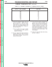
6. Carefully test for the correct voltages at
the power board as per Table F.4.
NOTE: Capacitor C3 (25000 mfd/100 V)
may hold a charge. Do not come in con-
tact with the capacitor terminals.
7. If the 65 VDC is low or not present at
plug J32, check the rectifier bridge and
C3 filter capacitor. See wiring diagram.
Also perform the
T1 Auxiliary
Transformer Test.
8. If any of the DC voltages are low, or not
present, at plug J31, the power board
may be faulty.
9. Install the case sides and top using the
3/8 in. nutdriver.
TEST PROCEDURE
1. Remove input power to the Power
Wave 455.
2. Using the 3/8 in. nutdriver, remove the
case sides and top.
3. Perform the
Capacitor Discharge
Procedure.
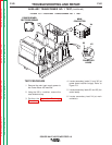
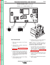
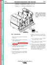
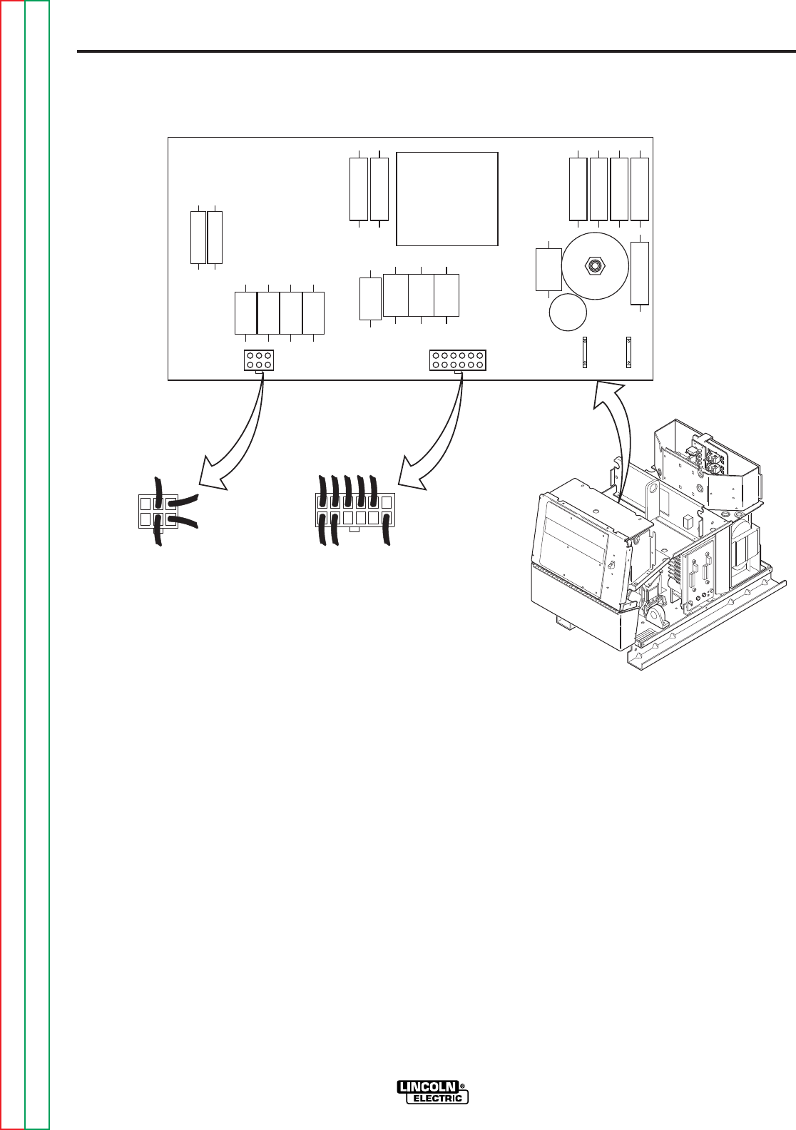
4. Locate the power board and plugs J31
and J32. Also locate leads #51 (black)
and #50 (white). Do not remove plugs
or leads from the power board. Refer
to Figure F.10.
5. Carefully apply the correct input voltage
to the Power Wave 455.
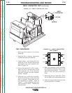
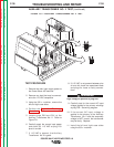
FIGURE F.10 — POWER BOARD TEST.
1 2 3 4 5
6
J31
7 8
910
11
12
J32
1
2
3
4
5
6
51
BK
50
WT
B2 B1
POWER BOARD TEST
(continued)
Return to Section TOC Return to Section TOC Return to Section TOC Return to Section TOC
Return to Master TOC Return to Master TOC Return to Master TOC Return to Master TOC