


F-49
TROUBLESHOOTING AND REPAIR
F-49
POWER WAVE 455/POWER FEED 10
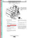
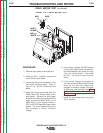
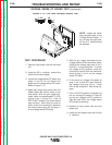
11. If the correct supply voltages are
applied to the current transducer, and
with the machine loaded, the feedback
voltage is missing or not correct, the
current transducer may be faulty. Also
make certain that lead #211 has conti-
nuity (zero ohms) between the current
transducer and the control board. See
wiring diagram.
12. Install the right side case cover using
the 3/8 in. nutdriver.
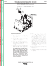
9. Check the feedback voltage from the
current transducer. With the Power
Wave system in a constant current
mode and the machine loaded to 250
amps, the current feedback voltage can
be read at plug P90.
A. Pin 3 (lead 211) to pin 4 (lead
216) should read 2.0 VDC (machine
loaded to 250 amps).
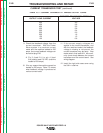
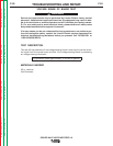
10. If for any reason the machine cannot be
loaded to 250 amps, Table F.5 shows
what feedback voltage is produced at
various current loads.
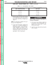
TABLE F.5 — CURRENT FEEDBACK AT VARIOUS OUTPUT LOADS.
CURRENT TRANSDUCER TEST
(continued)
EXPECTED TRANSDUCER FEEDBACK
OUTPUT LOAD CURRENT VOLTAGE
500 4.0
450 3.6
400 3.2
350 2.8
300 2.4
250 2.0
200 1.6
150 1.2
100 0.8
Return to Section TOC Return to Section TOC Return to Section TOC Return to Section TOC
Return to Master TOC Return to Master TOC Return to Master TOC Return to Master TOC