


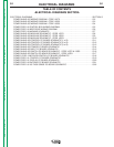
TROUBLESHOOTING AND REPAIR
F-95
POWER WAVE 455/POWER FEED 10
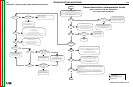
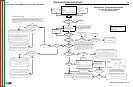
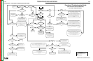
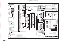
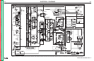
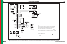
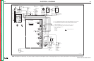
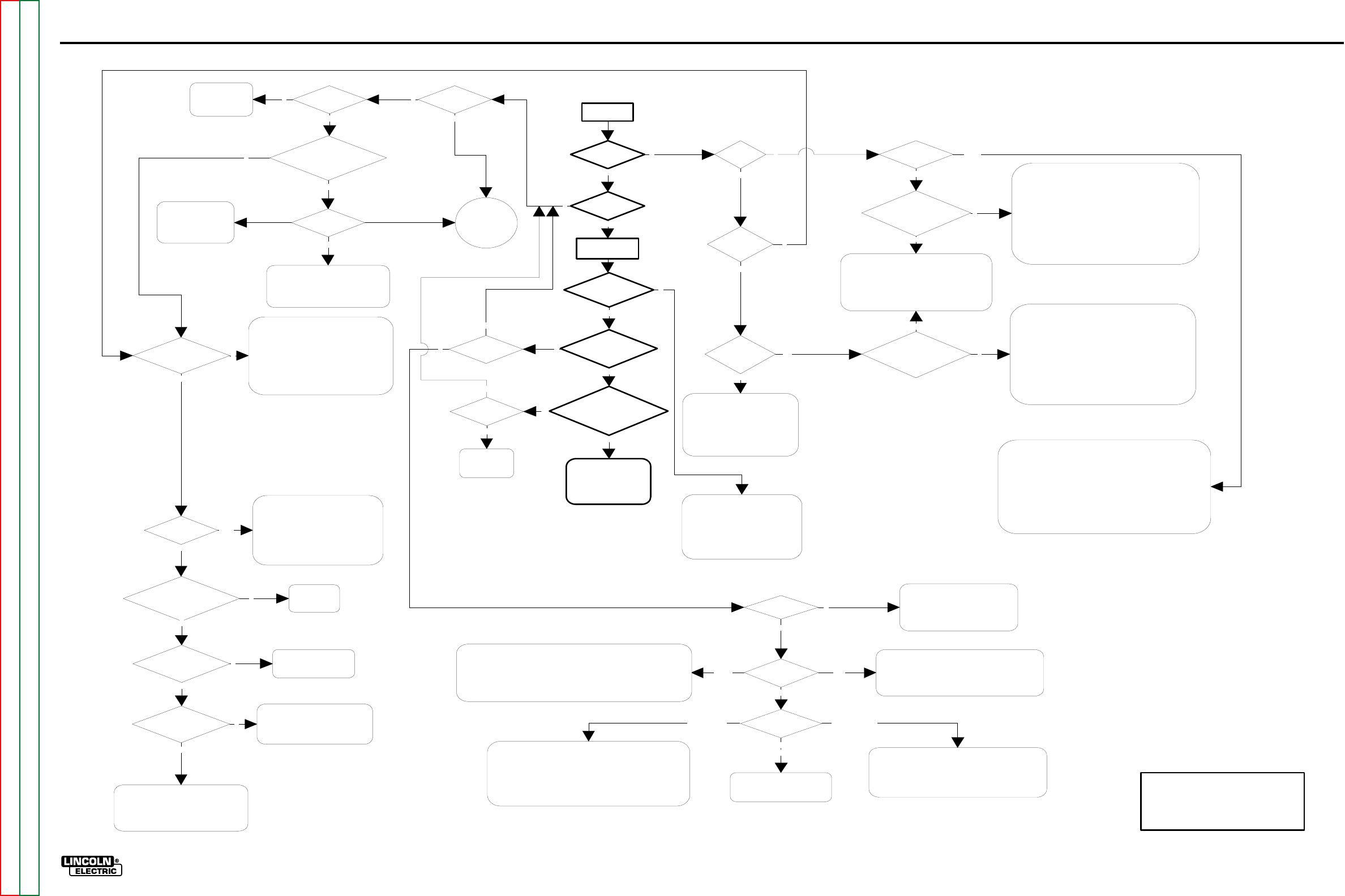
FLOWCHART - FUNCTIONAL TROUBLESHOOTING GUIDE
N
UI Status
on?
PS Status
on?
Check For
40VDC at UI
Control Board
Verify 12 VDC is being
supplied to UI Display
PCBD (J1 pin 7 to 8)
Y
OK
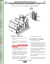
At this point, voltage is being supplied to the UI Control
Board, and the on board supply is properly converting it to
12Vdc, which has been verified at the display.
The Status light is not functioning, so the most likely
problem is that the UI Control board is "lost".Try reloading
the UI Software. If problem still exists, Replace the Control
board.
There is a remote possibility that a multiple fault exists in
the harness from the Display to the UI Control board, or in
any combination of the following: The harness, the Display
board
,
and the Status li
g
ht.
Turn On
Main UI Display
panel on?
Errors on UI
Display?
Can you adjust
WFS and Voltage?
Does Wire feed when
you pull the trigger?
Is there OCV from the
brass block to the work stud
with the trigger pulled
Error 100?
Status Light on the PS
on?
Condition of
Status light
Communication Fault.
Check Wiring and
Linc-Net Cables for
open circuit
Go To PS
Error
Interpretation
Guide.
Solid
Red
Error 006?
See UI Error
Chart for
additional error
codes.
Select a CV
Mode
Errors on UI
Display?
Errors on UI
Display?
FH Status On?
Be sure the trigger is engaged long enough to overcome any set preflow
delay, or turn the preflow timer off.
Check trigger circuit operation from the gun to the FH Control Board.
Perform the Drive Motor Test to verify motor voltage is present when the
trigger is pulled.
N
NN
Y
Y
Y
N
Y
Y
N
Condition of
Status Light?
Y
Y
5 Green LED's lit on
the PS Control
Board?
N
N
Verify 12 VDC is being
supplied to UI Display
PCBD (J1 pin 7 to 8)
Check connections from UI Control Board to
Display panel. If the display and Status light are
still not functioning, remove P4 from the UI
Control Board.
Check for 12 VDC at J4 pins 1 to 4 , and J4
pins 3 to 8 on the UI Control board. If voltage is
not present, replace UI Control Board
Solid Green
N
N
At this point, voltage is being supplied to the UI Control
Board, and the on board supply is properly converting it to
12Vdc. This has been verified by the condition of the Status
light and by measurement at the display.
Because the Status light indicates a healthy condition, the
problem is most likely in the harness from the Display to
the UI Control board or in the Display board itself. Check the
harness, and run the Display Panel Check.
There is a remote possibility that the Communications
Hardware on the UI Control board is not functioning
properly.
Y
Check PS breaker (CB1), Linc-Net
cables, wiring in UI and PS.
+40 VDC section of Power Board
may be malfunctioning, Perform
Power Board test
Not OK
System is functional. If
performance problems
exist see System
Performance
Troubleshooting guide
Y
Look for open
circuit in the
PS secondary
N
System is stuck in Remapping loop.
Most likely cause is the loss of the
+5Vcan Supply. Check J27 on PS
Control Board, check Power Board,
Etc.
Flashing Green
Y
Verify no Limits are set.
Check Harness for UI Control Board
to the Dislay Panel (specifically the
w
ires to the Encoder Board.
Run The Dual Encoder PC Board
Test
N
Flashing
Red and Green
N
Y
Y
N
Check Status Light and harness
Verify all connections to the PS Control Board
Perform Power Board test to verify correct
voltage levels
Reload the PS Software. If Problem still
exists, replace PS Control Board.
Y
Run Power
Board Test
Check/repair harness between:
The Power Board and the Control Board.
- AND/OR -
The Power Board and the wire feeder
receptacle (S1), including the output
circuit breaker (CB1).
Pass
N
Was 60-80 VDC at Power
Board input connector
Replace the
Power Board.
Fail
Y
Input power does not appear to be
supplied to aux. transformers
Check input power, check reconnect,
check Breakers, check Line Switch, etc.
Voltage at the input to
the Rectifier?
Voltage at the Power
Board Capacitor?
Check/repair harness
between the Power
Board and the Capacitor.
Check for 60 to 80 VDC at the
Output of the rectifier. If present,
check harness from rectifier to
Capacitor. If not replace rectifier
N
N
Y
Y
N
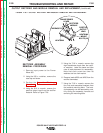
UNHEALTHY STATUS LIGHT WITH BLANK DISPLAY:
Improper system configuration (dipswitch settings) can result in
mapping errors that cause PS to continuously issue a system reset
command. The result is the UI gets stuck in a reset loop, usually
accompanied by a blank display with a green and/or red flashing
status light. Correct the system configuration.
Check the connections on wires 541 & 542, and pins A & B in the
Linc-Net control cable.
UI software may be corrupt. Reload UI soft ware
Other
N
FH Status
Condition?
FH does not appear to have power.
Check +40 VDC connections on
pins "D" & "E" of the Linc Net
receptacle in the FH.
Y
Check the continuity of the Shutdown circuit in the FH (wires
570 & 571). If the path between these wires is interrupted the
FH will not operate and the Status light will flash red while all
other nodes appear normal.
A rapidly flashing red Status light indicates the node needs to be
reprogrammed.
Functional Troubleshooting Guide
Y
(Semi Automatic PW-455, PW455/STT)
Key:
PS = Power Source
UI = User Interface (Control
Box)
FH
=
Feed Head
FH Status
Condition?
Check the system configuration.
If the FH is not recognized as part of a valid group, or if
improper dipswitch settings result in a duplicate or invalid
network assignment, a mapping error will be generated.
The FH has detected no activity from the
communication network.
Check the connections on wires 541 & 542, and pins
A & B in the Linc-Net control cable.
FH has a motor
overcurrent/overtemperature
error.
RedGreen
Flashing
Flashing GreenFlashing Red
Flashing
Red and Green
N
(For Codes 10555 and Below)
F-95
Return to Section TOC Return to Section TOC Return to Section TOC Return to Section TOC
Return to Master TOC Return to Master TOC Return to Master TOC Return to Master TOC