


F-84
TROUBLESHOOTING AND REPAIR
F-84
POWER WAVE 455/POWER FEED 10
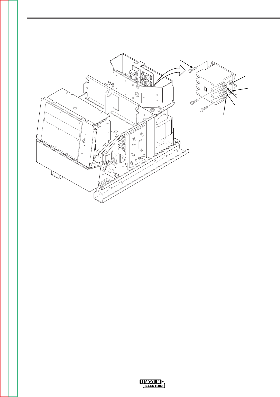
remove the small T2 lead. Label leads
for reassembly.
6. Remove the two small leads T1 and T3
from the quick disconnect terminals.
7. Remove leads 601, 601A, and X4, X4A
from the contactor coil terminals.
8. Remove leads L1A and L3A from the
contactor line side quick-disconnect ter-
minals.
9. Using the 5/16 in. nutdriver, remove the
three mounting screws holding the
input contactor to the metal housing
bracket.
10. Carefully remove the input contactor.
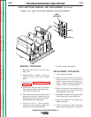
REMOVAL PROCEDURE
1. Remove input power to the Power
Wave 455.
2. Using the 3/8 in. nutdriver, remove the
case top, sides, and input access
panel.
3. Perform the
Capacitor Discharge
Procedure.
4. Using the slot head screwdriver,
remove the three input lines (L1, L2,
and L3) from the main contactor. Refer
to Figure F.24.
5. Using the slot head screwdriver,
remove the three heavy leads (T1, T2,
and T3) from the input contactor. Also
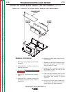
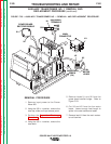
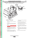
FIGURE F.24 — MAIN INPUT CONTACTOR REMOVAL AND REPLACEMENT.
MOUNTING
SCREW (3X)
L3
L2
L1
T1
T2
T3
X4/X4A
601/601A
MAIN INPUT CONTACTOR REMOVAL AND REPLACEMENT
(continued)
Return to Section TOC Return to Section TOC Return to Section TOC Return to Section TOC
Return to Master TOC Return to Master TOC Return to Master TOC Return to Master TOC