


A-16
INSTALLATION
POWER WAVE 455/POWER FEED 10
A-16
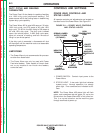
CV/GOUGE PANEL
NOTE: Installation Instructions for the standard
equipment panels will be required only if you have
removed a standard panel and wish to reinstall it.
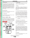
The CV/Gouge Panel fits into the lower position of
the Control Box.
Installation is as follows:
1. Turn off power.
2. Remove the two screws from the front of the
Control Box panel. Save the screws, discard the
old panel or save for future use.
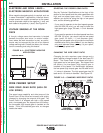
3. Tilt the new option panel away from the front
opening of the Control Box cabinet. Plug the
electrical connector into the proper connector on
the right side of the main printed circuit board
(12 pin). Make sure the connector latches in
place.
4. Position the panel to the opening, taking care not
to damage the switch connections on the back.
5. Align the screw holes, replace the two screws
and tighten.
OPTIONAL PANELS FOR CONTROL BOX
All optional panels for the control box are described
in the
Accessories
section of this manual.
STANDARD PANEL INSTALLATION
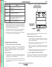
CONTROL/DISPLAY PANEL
NOTE: Installation Instructions for the standard
equipment panels will be required only if you have
removed a standard panel and wish to reinstall it.
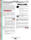
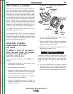
The Control/Display Panel fits into the upper or mid-
dle slots of the Control Box, and is used to adjust
WFS, Amps, Voltage, and Trim. It is also the location
of the Status indicator, a diagnostic tool provided for
system troubleshooting.
Installation is as follows:
1. Turn off power.
2. Remove the two screws from the front of the
blank option panel at the location you choose to
install your new panel, (top or middle), of the
Control Box cabinet. Discard the blank panel or
save for future use and save the screws.
3. Tilt the new panel away from the front opening of
the Control Box cabinet. Plug the electrical con-
nector into the proper connector on the right side
of the main printed circuit board (14 pin). Make
sure the connector latches in place.
4. Position the new panel, taking care not to dam-
age the printed circuit boards on the back and
align the screw holes.
5. Replace the two screws and tighten.
Return to Section TOC Return to Section TOC Return to Section TOC Return to Section TOC
Return to Master TOC Return to Master TOC Return to Master TOC Return to Master TOC