


E-4
THEORY OF OPERATION
E-4
POWER WAVE 455/POWER FEED 10
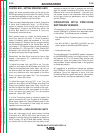
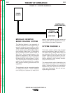
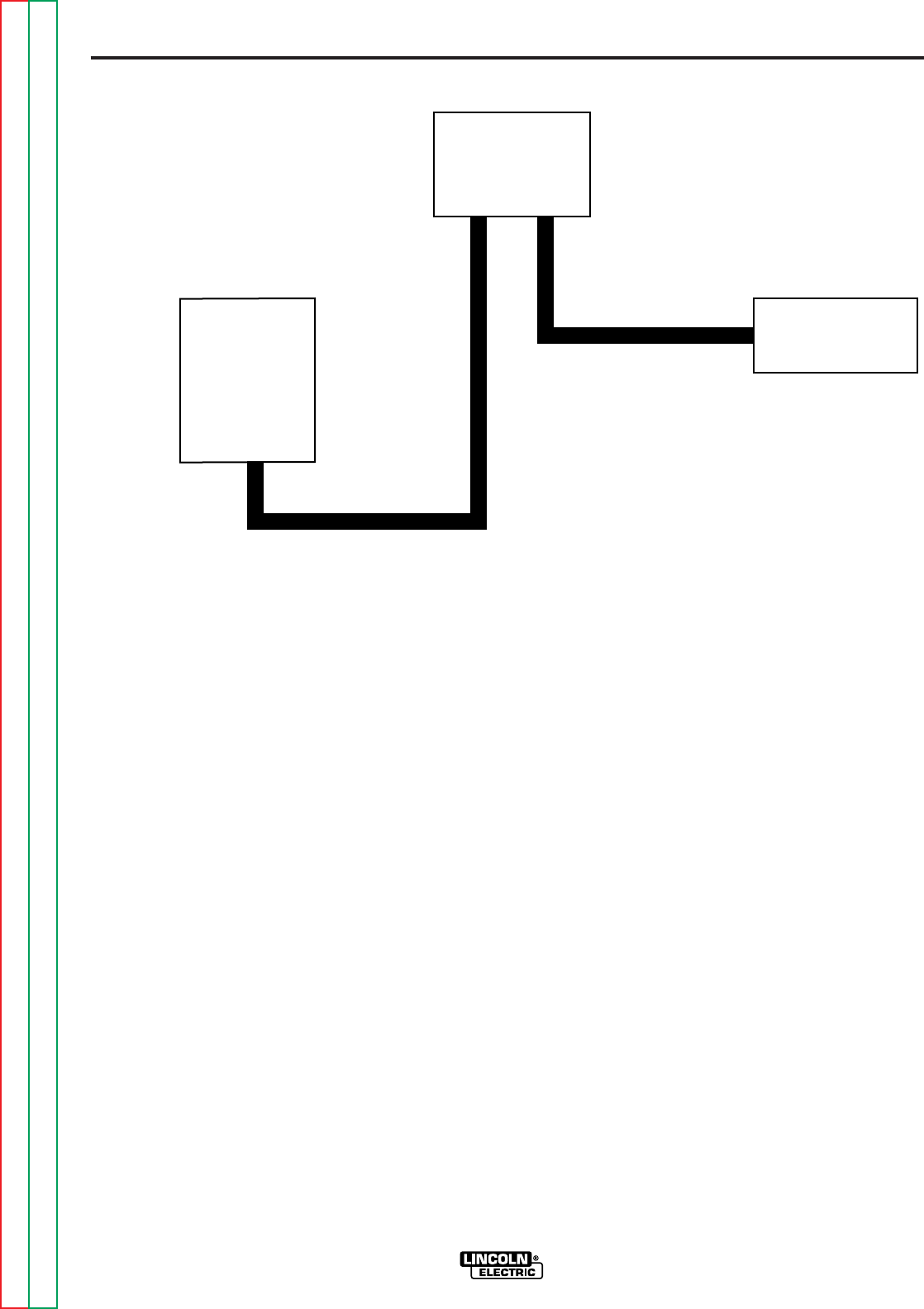
cables. All PC board power, communica-
tions and intelligence are transmitted via the
two cables.
This component configuration might be
used if the wire drive unit was mounted on a
boom and the Control Box located remotely
from the power source.
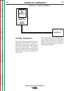
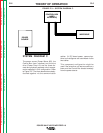
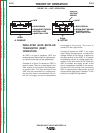
SYSTEM DIAGRAM C
The power source (Power Wave 455), the
Control Box (user interface) and the wire
drive (Power Feed 10) are the three dis-
crete and physically separate circuit compo-
nents employed in this configuration. Refer
to Figure E.3. The three elements are daisy-
chained together via the communication
FIGURE E.3 — SYSTEM DIAGRAM C.
POWER
SOURCE
CONTROL BOX
(USER
INTERFACE)
WIRE DRIVE
Return to Section TOC Return to Section TOC Return to Section TOC Return to Section TOC
Return to Master TOC Return to Master TOC Return to Master TOC Return to Master TOC