


E-6
THEORY OF OPERATION
E-6
POWER WAVE 455/POWER FEED 10
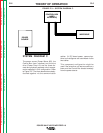
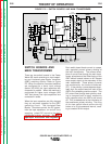
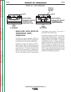
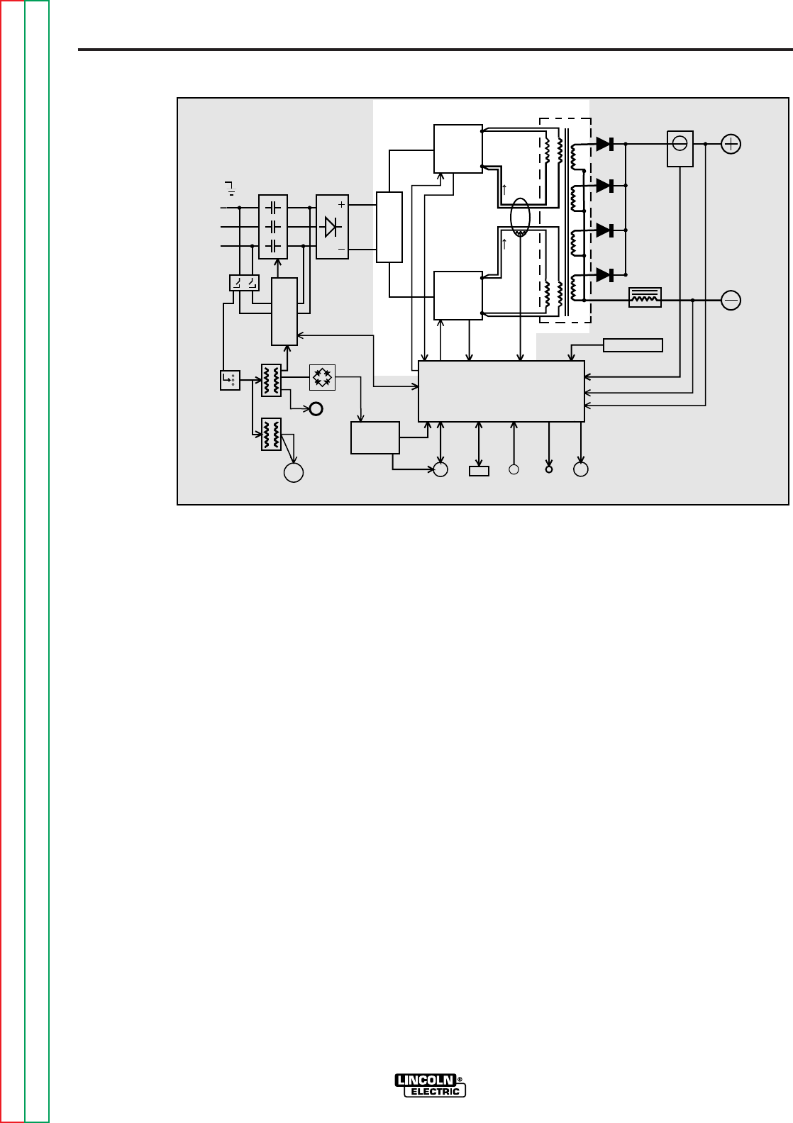
Each switch board feeds current to a sepa-
rate, oppositely wound primary winding of
the main transformer. The reverse direc-
tions of current flow through the main trans-
former primaries and the offset timing of the
IGBT switch boards induce an AC square
wave output signal at the secondary of the
main transformer. These primary currents
are monitored by the current transformer
(CT). If the primary currents become abnor-
mally high, the control board will shut off the
IGBTs, thus disabling machine output. The
DC current flow through each primary wind-
ing is clamped back to each respective
input capacitor when the IGBTs are turned
off. This is needed due to the inductance of
the transformer primary winding. The firing
of the two switch boards occurs during
halves of a 50 microsecond interval, creat-
ing a constant 20 kHz output.
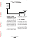
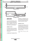
SWITCH BOARDS AND
MAIN TRANSFORMER
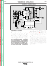
There are two switch boards in the Power
Wave 455, each containing an input capaci-
tor and insulated gate bipolar transistor
(IGBT) switching circuitry. Refer to Figure
E.5. When the machine reconnect switches
are configured for a lower input voltage
(below 300 VAC) the input capacitors are
connected in parallel. When the machine is
configured for higher input voltages (300
VAC and above) the input capacitors are
connected in series.
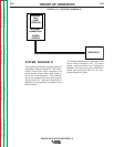
When the input capacitors are fully charged
they act as power supplies for the IGBT
switching circuit. The Insulated Gate
Bipolar Transistors switch the DC power,
from the input capacitors, “on and off” thus
supplying pulsed DC current to the main
transformer primary windings. See
IGBT
Operation Discussion and Diagrams
in
this section.
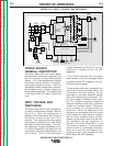
FIGURE E.5 — SWITCH BOARDS AND MAIN TRANSFORMER.
INPUT
CONTACTOR
INPUT
RECTIFIER
R
E
C
O
N
N
E
C
T
CONTROL BOARD
RIGHT
SWITCH
BOARD
LEFT
SWITCH
BOARD
MAIN
TRANSFORMER
CURRENT
SENSOR
CHOKE
OUTPUT
TERMINAL
OUTPUT
TERMINAL
POWER
BOARD
115VAC
RECEPTACLE
P
O
W
E
R
S
W
I
T
C
H
I
N
P
U
T
B
O
A
R
D
FAN
MOTOR
AUX.
TRANS.
AUX.
TRANS.
RECTIFIER
AUX.
RECONNECT
PRIMARY
CURRENT
SENSOR
WIRE FEEDER
RECEPTACLE
RS232
CONN.
THERMOSTATS
STATUS
LIGHT
THERMAL
LIGHT
CURRENT FEEDBACK
VOLTAGE FEEDBACK
65VDC
40VDC
CONTROL SIGNALS
PWM
DRIVE
CAPACITOR
VOLTAGE
FEEDBACK
CAPACITOR
VOLTAGE
FEEDBACK
PWM
DRIVE
VOLTAGE
SENSE
RECEPTACLE
#1
#2
S
W
I
T
C
H
Return to Section TOC Return to Section TOC Return to Section TOC Return to Section TOC
Return to Master TOC Return to Master TOC Return to Master TOC Return to Master TOC