


F-16
TROUBLESHOOTING AND REPAIR
F-16
POWER WAVE 455/POWER FEED 10
POWER FEED
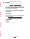
Observe all Safety Guidelines detailed throughout this manual.
If for any reason you do not understand the test procedures or are unable to perform the tests/repairs safely, contact the Lincoln Electric
Service Department for technical troubleshooting assistance before you proceed. Call 216-383-2531 or 1-800-833-9353.
-----------------------------------------------------------------------------------------------------------------------------
CAUTION
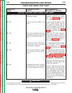
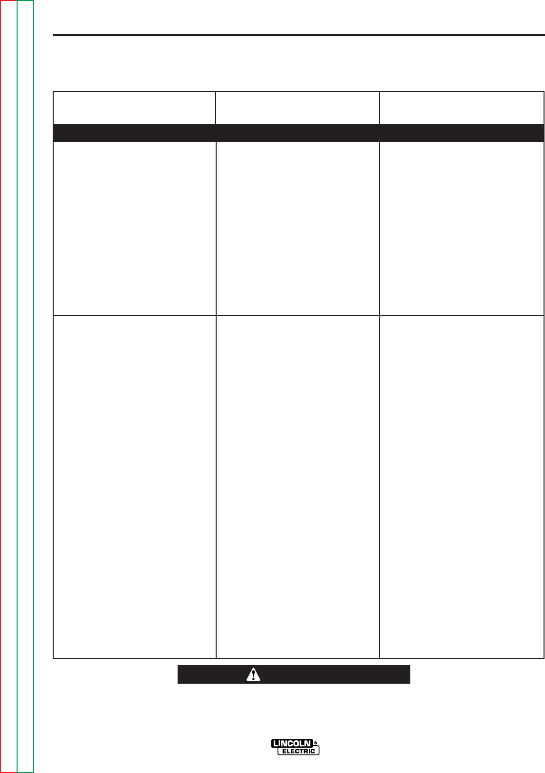
PROBLEMS
(SYMPTOMS)
POSSIBLE AREAS OF
MISADJUSTMENT(S)
RECOMMENDED
COURSE OF ACTION
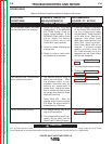
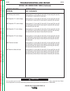
The displays are blank (not lit). The
wire feeds when the gun trigger is
activated.
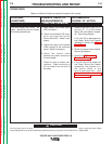
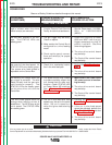
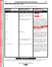
The dual procedure is not function-
al when using the remote Dual
Prodedure switch. The STATUS
LEDs are steady green on the
power source, Control Box and
wire drive units.
1. Check for loose or faulty con-
nections at plug J1 on the dis-
play board, to plug J4 on the
Control Box control board.
1. Make certain the the bat switch
on the Dual Procedure Panel is
in the middle position. This
enables the gun remote dual
procedure switch.
1. Check for 12 VDC at plug J1 pin
7 (lead #512+) to plug J1 pin 8
(lead #500-) on the display
board. If the 12 VDC is present,
then the display board may be
faulty.
2. If the 12 VDC is low or not pre-
sent, check for loose or faulty
connections on leads #512 and
#500.
3. The Control Box control board
may be faulty.
1. The remote Dual Procedure
switch may be faulty. Check
switch and associated leads.
2. The local dual procedure switch
may be faulty.
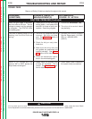
Remove power to the machine.
Disconnect plug J5 from the
Control Box control board.
Check for continuity (less than
one ohm) between pins 1 and 7
when the Dual Procedure switch
is in position “A”. Next check for
continuity (less than one ohm)
between pins 1 and 8 when the
Dual Procedure switch is in the
“B” position. If either of these
continuity tests fail, replace the
switch. When the switch is in
the center postion there should
not be any continuity between
pins.
3. The Control Box control board
may be faulty.
FUNCTION PROBLEMS (Continued)
Return to Section TOC Return to Section TOC Return to Section TOC Return to Section TOC
Return to Master TOC Return to Master TOC Return to Master TOC Return to Master TOC